A three phase transformer is used to transfer a large amount of power. The three phase transformer is required to step-up and step-down the voltages at various stages of a power system network. The three phase transformer is constructed in two ways.
- Three separate single phase transformer is suitably connected for three phase operation.
- A single three-phase transformer in which the cores and windings for all the three phases are merged into a single structure.
The three single-phase transformer can be used as a three-phase transformer when their primary and secondary winding are connected to each other. The three phase transformer supply has many advantages as compared to three single phase units like it requires very less space and also very lighter smaller and cheaper in size. The three phase transformer is mainly classified into two types, i.e., the core type transformer and the shell type transformer.
Core Type Three Phase Transformer
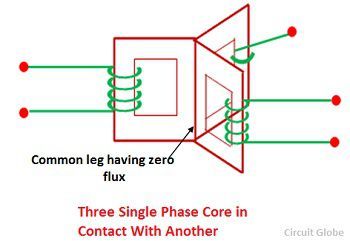
Consider a three single phase core type transformer positioned at 120° to each other as shown in the figure below. If the balanced three-phase sinusoidal voltages are applied to the windings, the fluxes φa, φb and φc will also be sinusoidal and balanced. If the three legs carrying these fluxes are combined, the total flux in the merged leg becomes zero. This leg can, therefore, be removed because it carries the no flux. This structure is not convenient for the core.
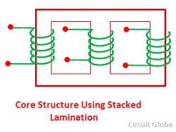
 The core of the three phase transformer is usually made up of three limbs in the same plane. This can be built using stack lamination. The each leg of this core carries the low voltage and high voltage winding. The low voltage windings are insulated from the core than the high voltage windings.
 The low windings are placed next to the core with suitable insulation between the core and the low voltage windings. The high voltage windings are placed over the low voltage windings with suitable insulation between them. The magnetic paths of the leg a and c are greater than that of leg b, the construction is not symmetrical, and there is a resultant imbalance in the magnetising current.
Shell type Three Phase Transformer
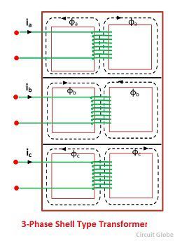
The shell type 3-phase transformer can be constructed by stacking three single phase shell transformer as shown in the figure below. The winding direction of the central unit b is made opposite to that of units a and c. If the system is balanced with phase sequence a-b-c, the flux will also be balanced
 The magnitude of this combined flux is equal to the magnitude of each of its components. The cross section area of the combined yoke is same as that of the outer leg and top and bottom section of the yoke. The imbalance in the magnetic path has very little effect on the performance of the three shell-type transformers. The windings of the shell type three phase transformer are either connected in delta or star as desired.
Also see: Three-Transformer Connections.
In 220kv to 11 kv Step Down Transformer in Which Suitable, Core Or Shell Type ?
Why are tranformer voltage rating in 11kv,33kv ,66kv …..
Very nice article, but there is one confusion in my mind that what is the type of mostly used distribution transformer.