The potential or voltage transformer is a step-down transformer used for transformation of voltage from a high value to fractional value. The measuring instrument like ammeter, voltmeter, wattmeter, etc. designs for low voltages. If the measuring apparatus connects to the high voltage lines for measurement, the devices may get burned or damage. Thus, the potential transformer uses for measurement.
The primary windings of the potential transformer are directly connected to the measurand line and their second terminals connect to the meter. The potential transformer converts the high voltage of the measurand line into a fractional value which is determined by the measuring instrument.
The construction of potential transformer and the power transformer are almost same, but they have small differences like
- The constructional of the potential transformer can be done by considering the cost, efficiency and their regulation. Whereas the potential transformer is designed by keeping in view their performance parameters, i.e., the ratio of the voltage and number of turns remains constant, and the phase difference between the input and output signal becomes small.
- The temperature rise problem occurs in the power transformer because of overloading. As the output of the potential transformer is small, thereby the problem of overheating not happens in it.
Parts of Potential Transformer
The following are the essential parts of the potential transformer.
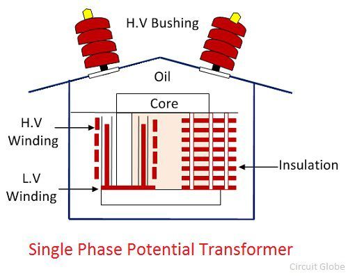 1. Core – The core of the potential transformer may be of core type or shell type. In a core type transformer, the windings surrounding the core and in the shell type transformer the core surrounded the winding. The shell type transformer designs for low voltage works while the core type transformer is used for high voltage applications.
2. Windings – The primary and secondary windings are placed coaxially for reducing the leakage reactance of the potential transformer.
Note Leakage Reactance – All the flux from the primary winding of the transformer is not linked with their secondary windings. The small portion of the flux link with any one of the winding. This portion of the flux is known as the leakage flux.
The leakage flux creates the self-reactance in the winding in which they link. The term reactance means the opposition occurs by the circuit element because of the change of the voltage and current. This self-reactance is known as the leakage reactance.
In low voltage transformer, the insulation is placed next to the core for reducing the problems of insulation.The single coil is used as the primary winding of the low potential transformer. But in the large potential transformer, the single coil is subdivided into small parts for reducing the insulation between the layer.
3. Insulation – The cotton tape and the cambric materials are used as insulation between the winding of the potential transformer. The compound insulation is not used in low voltage transformer. The high voltage transformer uses oil as an insulation medium. The transformer having a rating higher than 45kVA uses porcelain material as an insulator.
4. Bushing – The bushing is an insulated device through which the transformer is connected to the external circuit. The bushings of the transformer are made of porcelain material. The transformer which uses the oil as an insulating medium uses the oil filled bushing.
Two bushings transformer is used in the system when the line through which it is connected is not at ground potential.The transformer which connects to the ground neutral uses only one high voltage bushing.
Connection of Potential Transformer
The primary winding of the potential transformer connects to the high voltage transmission line whose voltage needs to be measured. The secondary of the transformer connects to the meter through which the magnitude of the voltage is determined.