Parallel Resonance means when the circuit current is in phase with the applied voltage of an AC circuit containing an inductor and a capacitor connected together in parallel.
Let us understand the Parallel Resonance with the help of a circuit diagram shown below:
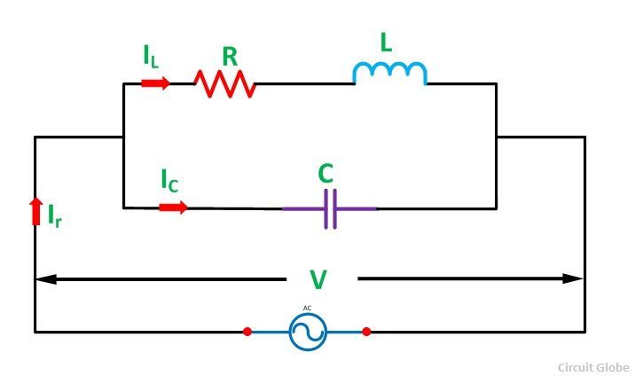 Consider an Inductor of L Henry having some resistance of R ohms connected in parallel with a capacitor of capacitance C farads. A supply voltage of V volts is connected across these elements. The circuit current Ir will only be in phase with the supply voltage when the following condition given below in the equation is satisfied.
![]()
Contents:
- Phasor Diagram
- Frequency at Resonance Condition in Parallel resonance Circuit
- Effect of Parallel Resonance
The phasor diagram of the given circuit is shown below:
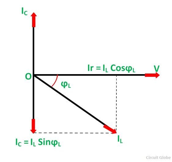 At the Resonance condition, the circuit draws the minimum current as under this (resonance) condition the reactive component of current is suppressed.
Frequency at Resonance Condition in Parallel resonance Circuit
The value of inductive reactance XL = 2πfL and capacitive reactance XC = 1/2πfC can be changed by changing the supply frequency. As the frequency increases, the value of XL and consequently the value of ZL increases. As a result, there is a decrease in the magnitude of current I2 and this I2 current lags behind the voltage V.
On the other hand, the value of capacitive reactance decreases and consequently the value of IC increases.
At some frequency, fr called resonance frequency.
![]()
Where,
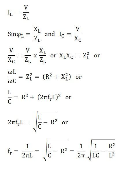
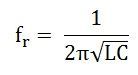
If R is very small as compared to L, then resonant frequency will be
Effect of Parallel Resonance
At parallel resonance line current Ir = IL cosϕ or
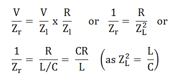
Therefore, the circuit impedance will be given as:
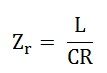
The following conclusions are made from the above discussion about the Parallel Resonance.
- The circuit impedance is purely resistive because there is no frequency term present in it. If the value of inductance, capacitance and resistance is in Henry, Farads and Ohm then the value of circuit impedance Zr will be in Ohms.
- The value of Zr will be very high because the ratio L/C is very large at parallel resonance.
- The value of circuit current, Ir = V/Zr is very small because the value of Zr is very high.
- The current flowing through the capacitor and the coil is much greater than the line current because the impedance of each branch is quite lower than that of circuit impedance Zr.
Since the parallel resonant circuit can draw a very small current and power from the mains, therefore, it is also called as Rejector Circuit.
nice stuffs 🙂
Sir. Resonance pin paralle acl circuit ko impedence se kaise solve kaenge
good explanation
Agree, nice stuff.
very clear, thank you
I have never commented on any article yet, but your article is so impressive.
So I can’t resist myself to comment.
Very understanding notes 👌👌👌👌
Thank you.
I enjoyed this article. Thanks