Definition: A magnetic circuit having two or more than two paths for the magnetic flux is called a parallel magnetic circuit. Its behaviour can be compared to the parallel electric circuit. The parallel magnetic circuit contains different dimensional areas and materials having various numbers of paths.
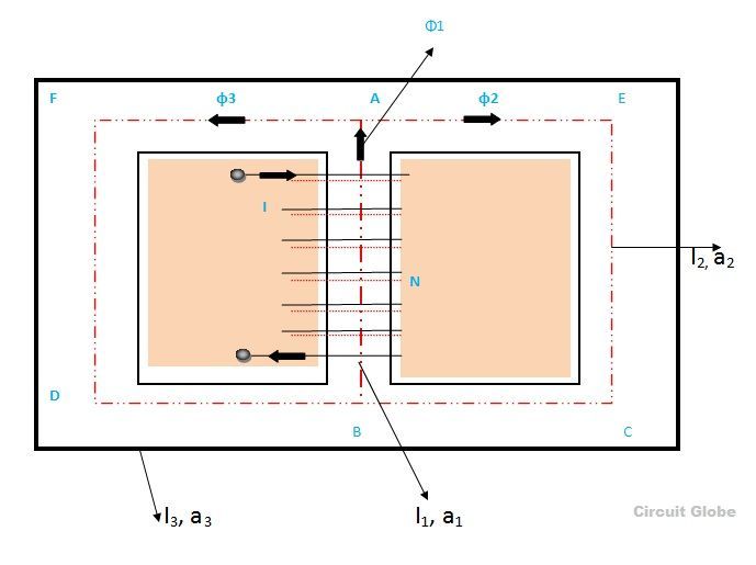
The above figure shows a parallel magnetic circuit. In this circuit, a current-carrying coil is wound on the central limb AB. This coil sets up the magnetic flux φ1 in the central limb of the circuit. The flux φ1 which is in the upward direction is further divided into two paths namely ADCB and AFEB. The path ADCB carries flux φ2, and the path AFEB carries flux φ3. It is clearly seen fro the above circuit that
φ1 = φ2 + φ3
The two magnetic paths ADCB and AFEB form the parallel magnetic circuit, thus, the ampere-turns (ATs) required for this parallel circuit are equal to the ampere-turns (ATs) required for any one of the paths.
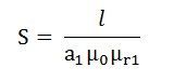
As we know, reluctance is
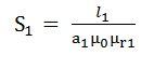
If S1 = reluctance of path BA will be
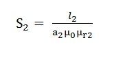
S2 =reluctance of path ADCB will be
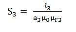
S3 = reluctance of the path AFEB will be
Therefore, the total MMF or the total Ampere turns required in the parallel magnetic circuit will be the sum of all the individual parallel paths.
Total mmf required = mmf required for the path BA +mmf required for the path ADCB + mmf required for the path AFEB
![]()
Where φ1. Φ2, φ3 is the flux and S1, S2, S3 are the reluctances of the parallel path BA, ADCB and AFEB respectively.
Nice Content.
thanks for it