The crucial difference between series and parallel circuit exist on the basis of orientation of the components in the circuit. In a series circuit, the multiple components are connected in a cascaded manner i.e., the tail of a component is connected to the head of the other.
While in a parallel circuit, the multiple components are connected in head to head and tail to tail orientation.
Content: Series Vs Parallel Circuit
| Basis for Comparison | Series Circuit | Parallel Circuit |
|---|---|---|
| Component Orientation | The components are connected in one after the other manner. | Here the components are connected in head to head and tail to tail manner. |
| Current | Same current flows through all the components in the circuit. | Different current flows through each component in the circuit. |
| Voltage | Different potential difference (voltage) exist across each component. | The potential difference (voltage) existing across the various component in the circuit is same. |
| Number of paths | Single | Multiple (depends on number of components). |
| Fault | Fault in one of the circuit components causes hindrance in operation of complete circuit. | Fault in a single component does not hinder the operation of rest of the circuit. |
| Troubleshooting | Difficult. | Quite easy. |
| Equivalent resistance | The equivalent resistance is always more than highest value of resistance in the series connection. | The equivalent resistance always has a less value than any of the single resistors connected parallely. |
Definition of Series Circuit
In the series circuit, the components in the circuit are connected one after the other or we can say in a cascaded fashion. More specifically we can say that a series circuit allows the connection in a manner that tail of one component is directly connected to the head of the other and so on corresponding to the two ends of the battery.
The figure below shows the series connection of 4 resistors in a circuit:
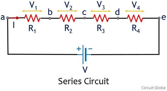
As we can clearly see that the components are cascaded in a single line, thus same current, I will flow through all the resistors of the series network. While different potential difference exists between the various resistors of the circuit.
It can be understood in a way that if the same current is flowing among all the resistors, so the drop across each resistor will depend on the resistance offered by each resistor in the circuit. Thus, we can say that, in a series circuit due to the presence of a single path, the same current flows through all the components. Thereby giving rise to the existence of different potential difference (voltage) across each component.
Definition of Parallel Circuit
In a parallel circuit, the components are arranged in a way that the heads of each component are connected together with a common point. While the tails are connected together with another common point. Thereby forming multiple parallel branches in the circuit. The figure here shows the parallel connection of 4 resistors in a circuit:
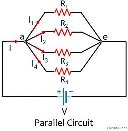
As we can see here that the parallel circuit is having 4 branches and different current is flowing through each branch. But as the branches are sharing common points thus the same potential exists across the two points wrt the two ends of the battery potential.
It can also be understood in a way that if the same potential difference is existing across each resistor of the circuit. Then the actual current flowing through each branch will automatically depend on the resistance offered by each resistor in the circuit.
Therefore, we can say that due to the existence of multiple branches in the circuit, the overall current from the supply gets divided into multiple branches, as the voltage across the points is the same.
Key Differences Between Series and Parallel Circuit
- The components in a series circuit are arranged in a single path from one end of supply to another end. However, the multiple components in a parallel circuit are arranged in multiple paths wrt the two end terminals of the battery.
- In a series circuit, a common current flows through all the components of the circuit. While in a parallel circuit, a different amount of current flows through each parallel branch of the circuit.
- In the series circuit, different voltage exists across each component in the circuit. Whereas in the parallel circuit, the same voltage exists across the multiple components in the circuit.
- A fault in one of the components of the series circuit causes hindrance in the operation of a complete circuit. As against fault in a single component in a parallel network do not hinder the functioning of another part of the circuit.
- The detection of a fault in case of a series circuit is difficult, but it is quite easy in parallel circuits.
- The equivalent resistance in case of a series circuit is always more than the highest value of resistance in the series connection. While the equivalent resistance in the parallel circuit is always less than any of the individual resistances in parallel combination.
Conclusion
So, from this discussion, we can say that, in the series circuit, flowing current remains the same at each part of the circuit. While in parallel circuits, the voltage across two endpoints of the branches is the same as the supplied voltage.
Well answered
This was so easy to understand very well detailed, all I’d need for my formative tomorrow!