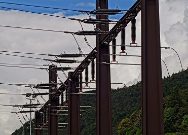
Definition: An electrical bus bar is defined as a conductor or a group of conductor used for collecting electric power from the incoming feeders and distributes them to the outgoing feeders. In other words, it is a type of electrical junction in which all the incoming and outgoing electrical current meets. Thus, the electrical bus bar collects the electric power at one location.
The bus bar system consists the isolator and the circuit breaker. On the occurrence of a fault, the circuit breaker is tripped off and the faulty section of the busbar is easily disconnected from the circuit.
The electrical bus bar is available in rectangular, cross-sectional, round and many other shapes. The rectangular bus bar is mostly used in the power system. The copper and aluminium are used for the manufacturing of the electrical bus bar.
 The most common of the bus-bars are 40×4mm (160 mm2); 40×5 mm (200 mm2) ; 50×6 mm (300mm2) ; 60×8 mm (480 mm2) ; 80×8 (640 mm2) and 100×10 mm (1000 mm2).
The various types of busbar arrangement are used in the power system. The selection of the bus bar is depended on the different factor likes reliability, flexibility, cost etc. The following are the electrical considerations governing the selection of any one particular arrangement.
- The bus bar arrangement is simple and easy in maintenance.
- The maintenance of the system did not affect their continuity.
- The installation of the bus bar is cheap.
The small substation where continuity of the supply is not essential uses the single bus bar. But in a large substation, the additional busbar is used in the system so that the interruption does not occur in their supply. The different type of electrical busbar arrangement is shown in the figure below.
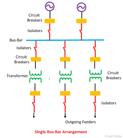
Single Bus-Bar Arrangement
The arrangement of such type of system is very simple and easy. The system has only one bus bar along with the switch. All the substation equipment like the transformer, generator, the feeder is connected to this bus bar only. The advantages of single bus bar arrangements are
- It has low initial cost.
- It requires less maintenance
- It is simple in operation
 Drawbacks of Single Bus-Bars Arrangement
- The only disadvantage of such type of arrangement is that the complete supply is disturbed on the occurrence of the fault.
- The arrangement provides the less flexibility and hence used in the small substation where continuity of supply is not essential.
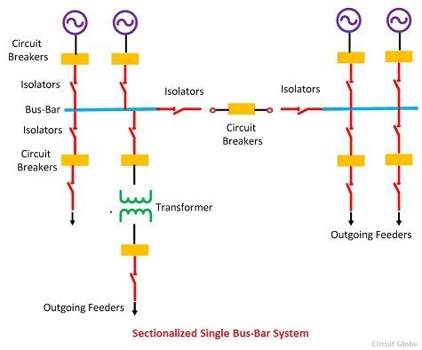
Single Bus-Bar Arrangement with Bus Sectionalized
In this type of busbar arrangement, the circuit breaker and isolating switches are used. The isolator disconnects the faulty section of the busbar, hence protects the system from complete shutdown. This type of arrangement uses one addition circuit breaker which does not much increase the cost of the system.
 Advantage of single Bus-bar Arrangement with Bus Sectionalization
The following are the advantages of sectionalized bus bar.
- The faulty section is removed without affecting the continuity of the supply.
- The maintenance of the individual section can be done without disturbing the system supply.
- The system has a current limiting reactor which decreases the occurrence of the fault.
Disadvantages of Single Bus-Bar Arrangement with Sectionalization
- The system uses the additional circuit breaker and isolator which increases the cost of the system.
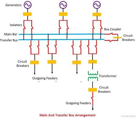
Main and Transfer Bus Arrangement
Such type of arrangement uses two type of busbar namely, main busbar and the auxiliary bus bar. The busbar arrangement uses bus coupler which connects the isolating switches and circuit breaker to the busbar. The bus coupler is also used for transferring the load from one bus to another in case of overloading. The following are the steps of transferring the load from one bus to another.
- The potential of both the bus bar kept same by closing the bus coupler.
- The bus bar on which the load is transferred is kept close.
- Open the main bus bar.
Thus, the load is transferred from the main bus to reserve bus.
 Advantages of Main and Transfer Bus Arrangement
- The continuity of the supply remains same even in the fault. When the fault occurs on any of the buses the entire load is shifted to the another bus.
- The repair and maintenance can easily be done on the busbar without disturbing their continuity.
- The maintenance cost of the arrangement is less.
- The potential of the bus is used for the operation of the relay.
- The load can easily be shifted on any of the buses.
Disadvantages of Main and Transfer Bus Arrangement
- In such type of arrangements, two bus bars are used which increases the cost of the system.
- The fault on any of the bus would cause the complete shutdown on the whole substation.
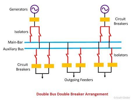
Double Bus Double Breaker Arrangement
This type of arrangement requires two bus bar and two circuit breakers. It does not require any additional equipment like bus coupler and switch.
 Advantages of Double Bus Double Breaker
- This type of arrangement provides the maximum reliability and flexibility in the supply. Because the fault and maintenance would not disturb their continuity.
- The continuity of the supply remains same because the load is transferrable from one bus to another on the occurrence of the fault.
Disadvantages of double bus Double breaker
- In such type of arrangement two buses and two circuit breakers are used which increases the cost of the system.
- Their maintenance cost is very high.
Because of its higher cost, such type of bus-bars is seldom used in substations.
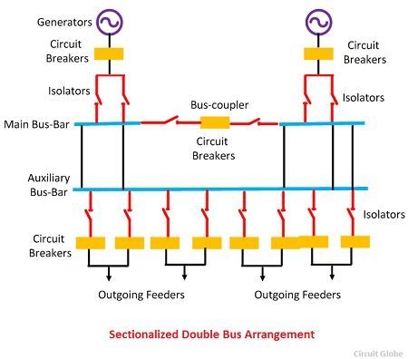
Sectionalized Double Bus Bar Arrangement.
In this type of bus arrangement, the sectionalized main bus bar is used along with the auxiliary bus bar. Any section of the busbar removes from the circuit for maintenance and it is connected to any of the auxiliary bus bars. But such type of arrangement increases the cost of the system. Sectionalization of the auxiliary bus bar is not required because it would increase the cost of the system.
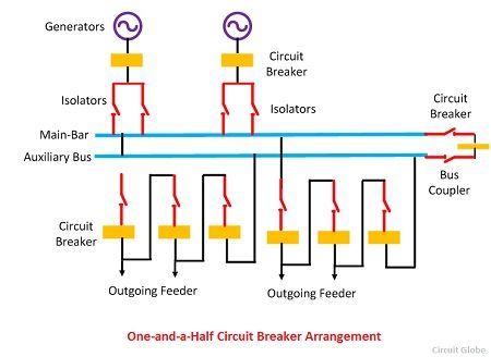
 One and a Half Breaker Arrangement
In this arrangement, three circuit breakers are required for two circuits. The each circuit of the bus bar uses the one and a half circuit breaker. Such type of arrangement is preferred in large stations where power handled per circuit is large.
 Advantages of One and a Half Breaker Arrangement
- It protects the arrangement against the loss of supply.
- The potential of the bus bar is used for operating the relay.
- In such type of arrangement, the additional circuits are easily added to the system.
Disadvantages of One and a Half Breaker Arrangement
- The circuit becomes complicated because of the relaying system.
- Their maintenance cost is very high.
Ring Main Arrangement
In such type of arrangement, the end of the bus bar is connected back to the starting point of the bus to form a ring.
 Advantages of Ring Main Arrangement
- Such type of arrangement will provide two paths for the supply. Thus the fault will not affect their working.
- The fault is localized for the particular section. Hence the complete circuit is not affected by the fault.
- In this arrangement, a circuit breaker can be maintained without interrupting the supply.
Disadvantages of Ring Main Arrangement
- Difficulties occur in the addition of the new circuit.
- Overloading occurs on the system if any of the circuit breakers is opened.
Mesh Arrangement
In such type of arrangement, the circuit breakers are installed in the mesh formed by the buses. The circuit is tapped from the node point of the mesh. Such type of bus arrangement is controlled by four circuit breakers.
 When a fault occurs on any section, two circuit breakers have to open, resulting in the opening of the mesh. Such type of arrangement provides security against bus-bar fault but lacks switching facility. It is preferred for substations having a large number of circuits.
i have learned a lot, thanks,
say something concerning overhead cabling,ties, insultion
Very nicely written, quite understandable. kudos
I am interested in syncronchek relay
Simply great!!!!
what is segregated bus duct and nonsegregated bus duct..?
Segregated Busduct is a metallic enclosure where all the three phases busbars are commonly enclosed. These phases are isolated by the help of the non-magnetic metal barriers. The construction of the non-segregated bus duct is similar to that of the segregated bus duct the only difference is that instead of metallic barriers it uses air as an insulator between the phases.
Nicely written
I am an Electrical Engineering student in the university of Yaounde 1 in Central Africa pursuing my Master’s degree, at the moment i am writing my THESIS with the topic INTERCONNECTION OF ELECTRICAL GRIDS.
I would like to seek your assistance on how to go about my thesis topic in order to achieve objective of supplying power to consumers:
* Reliably, economically, safely, and efficiently,
* minimize disruptions to the transmission and interconnected systems.
* minimize damage to the power system equipment.
If i can get a PDF on the said topic above sent to my email that will also help greatly.
Best Regards,
James.
Very Educated and understanding
It’s nicely explained.
And easy to understand.
Thank you so much ❤….
Please give information about Main bus bar and emergency bus bar coupling
Nice article
thank you so much
Thank you so much for the clearly explained information. Can I know if it is okay if I replace the bus-coupler with a circuit breaker for software simulations?
It’s a very knowledgeable site about electrical equipment.
Can a low voltage panel have a common busbar for both grid source and generator source that can be used alternatively….