Parallel Operation of a Single Phase Transformer means that the two or more transformers having the same polarities, same turn ratios, same phase sequence and the same voltage ratio are connected in parallel with each other.
The circuit diagram of two single-phase transformer A and B connected in parallel are shown below:
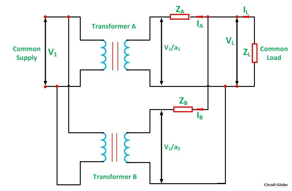 Let,
Let,
a1 is the turn ratio of the transformer A
a2 is the turn ratio of transformer B
ZA is the equivalent impedance of the transformer A referred to secondary
ZB is the equivalent impedance of the transformer B referred to secondary
ZL is the load impedance across the secondary
IA is the current supplied to the load by the secondary of the transformer A
IB is the current supplied to the load by the secondary of the transformer B
VL is the secondary load voltage
IL is the load current
Applying Kirchhoff’s Current Law,
By Kirchhoff’s Voltage Law,
Now putting the value of IB from the equation (1) in equation (3) we will get,
Solving equations (2) and (4) we will get,
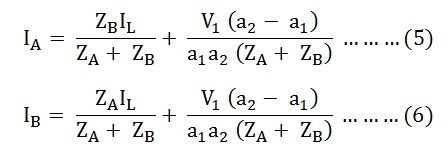
The current IA and IB have two components. The first component represents the transformers share of the load currents and the second component is a circulating current in the secondary windings of the single-phase transformer.
The undesirable effects of the circulating currents are as follows
- They increase the copper loss.
- The circulating current overloads the one transformer and reduce the permissible load kVA.
Equal Voltage Ratio
In order to eliminate circulating currents, the voltage ratios must be identical. That is a1=a2
Under this condition,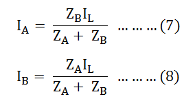
Equating equation (7) and (8) we will get: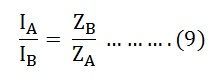
From the above equation (9), it is clear that the transformer currents are inversely proportional to the transformer impedance. Thus, for the efficient parallel operation of the two single-phase transformers, the potential differences at full load across the transformer internal impedance should be equal.
This condition ensures that the load sharing between the two single-phase transformer is according to the rating of each transformer. If the per-unit equivalent impedance are not equal, then the transformer will not share the load in proportion to their kVA ratings. As a result, the overall rating of the transformer bank will be reduced.
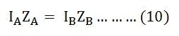
Equation (9) can also be written as
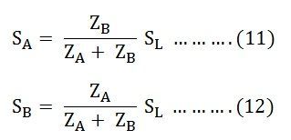
The current in the equations (7) and (8) is changed into volt-amperes by multiplying the two equations by the common load voltage VL.
Therefore, we know that,
The total load in volt-ampere (VA) is
![]()
The volt-ampere of transformer A is
![]()
Similarly, the volt-ampere of transformer B is
![]()
Hence, the various equations will be written as shown below
Equating the equation (11) and (12) we will get
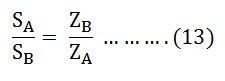
Equation (13) tells that the volt-ampere load on each single-phase transformer is inversely proportional to its impedance.
Hence, to share the load in proportion to their ratings, the transformers should have the impedance which is inversely proportional to their ratings.
super
Wow, nice discussion of the subject; very helpful.
It was really helpful, thanks 🙂