The three phase transformer consists three transformers either separate or combined with one core. The primary and secondary of the transformer can be independently connected either in star or delta. There are four possible connections for a 3-phase transformer bank.
- Δ – Δ (Delta – Delta) Connection
- Υ – Υ (Star – Star) Connection
- Δ – Υ (Delta – Star) Connection
- Υ – Δ (Star – Delta ) Connection
The choice of connection of three phase transformer depends on the various factors likes the availability of a neutral connection for grounding protection or load connections, insulation to ground and voltage stress, availability of a path for the flow of third harmonics, etc. The various types of connections are explained below in details.
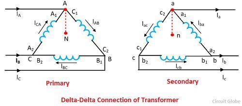
1. Delta-Delta (Δ-Δ) Connection
The delta-delta connection of three identical single phase transformer is shown in the figure below. The secondary winding a1a2 is corresponding to the primary winding A1A2, and they have the same polarity. The polarity of the terminal a connecting a1 and c2 is same as that connecting A1 and C2. The figure below shows the phasor diagram for lagging power factor cosφ.
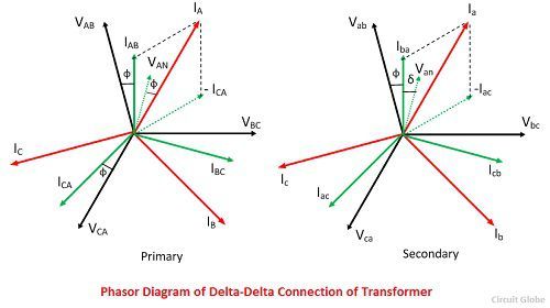
The magnetising current and voltage drops in impedances have been neglected. Under the balanced condition, the line current is √3 times the phase winding current. In this configuration, the corresponding line and phase voltage are identical in magnitude on both primary and secondary sides.
The secondary line-to-line voltage is in phase with the primary line-to-line voltage with a voltage ratio equal to the turns ratio.
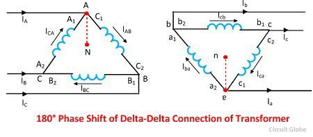
If the connection of the phase windings is reversed on either side, the phase difference of 180° is obtained between the primary and the secondary system. Such a connection is known as an 180º connection.
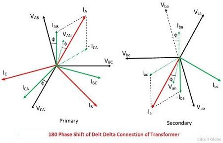
The delta-delta connection with 180º phase shift is shown in the figure below. The phasor diagram of a three phase transformer shown that the secondary voltage is in phase opposition with the primary voltage.
The delta-delta transformer has no phase shift associated with it and problems with unbalanced loads or harmonics.
Advantages of delta–delta connection of transformer
The following are the advantages of the delta-delta configuration of transformers.
- The delta-delta transformer is satisfactory for a balanced and unbalanced load.
- If one transformer fails, the remaining two transformers will continue to supply the three-phase power. This is called an open delta connection.
- If third harmonics present, then it circulates in a closed path and therefore does not appear in the output voltage wave.
The only disadvantage of the delta-delta connection is that there is no neutral. This connection is useful when neither primary nor secondary requires a neutral and the voltage are low and moderate.
2. Star-Star (Υ-Υ) Connection of Transformer
The star-star connection of three identical single phase transformer on each of the primary and secondary of the transformer is shown in the figure below.The phasor diagram is similar as in delta-delta connection.
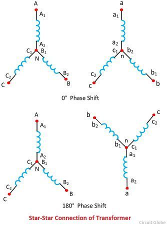
The phase current is equal to the line current, and they are in phase. The line voltage is three times the phase voltage. There is a phase separation of 30º between the line and phase voltage.The 180º phase shift between the primary and secondary of the transformer is shown in the figure above.
Problems Associated With Star-Star Connection
The star-star connection has two very serious problems. They are
- The Y-Y connection is not satisfactory for the unbalance load in the absence of a neutral connection. If the neutral is not provided, then the phase voltages become severely unbalance when the load is unbalanced.
- The Y-Y connection contains a third harmonics, and in balanced conditions, these harmonics are equal in magnitude and phase with the magnetising current. Their sum at the neutral of star connection is not zero, and hence it will distort the flux wave which will produce a voltage having a harmonics in each of the transformers
The unbalanced and third harmonics problems of Y-Y connection can be solved by using the solid ground of neutral and by providing tertiary windings.
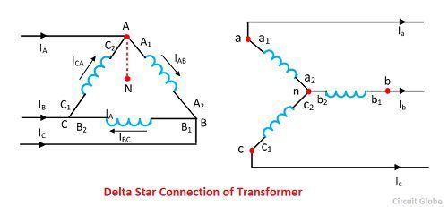
3. Delta-Star (Δ-Υ) Connection
The ∆-Y connection of the three winding transformer is shown in the figure below. The primary line voltage is equal to the secondary phase voltage. The relation between the secondary voltages is VLS= √3 VPS.
The phasor diagram of the ∆-Y connection of the three phase transformer is shown in the figure below. It is seen from the phasor diagram that the secondary phase voltage Van leads the primary phase voltage VAN by 30°. Similarly, Vbn leads VBN by 30º and Vcn leads VCN by 30º.This connection is also called +30º connection.
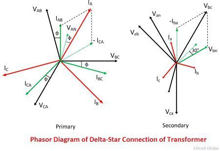
By reversing the connection on either side, the secondary system voltage can be made to lag the primary system by 30°. Thus, the connection is called -30° connection.
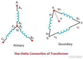
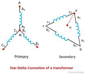
4. Star-Delta (Υ-Δ) Connection
The star-delta connection of three phase transformer is shown in the figure above. The primary line voltage is √3 times the primary phase voltage. The secondary line voltage is equal to the secondary phase voltage. The voltage ratio of each phase is
Therefore line-to-line voltage ratio of Y-∆ connection is
![]()
The phasor diagram of the configuration is shown in the figure above. There is a phase shift of 30 lead exists between respective phase voltage. Similarly, 30° leads exist between respective phase voltage. Thus the connection is called +30º connection.
The phase shows the star-delta connection of transformer for a phase shift of 30° lag. This connection is called – 30° connection. This connection has no problem with the unbalanced load and thirds harmonics. The delta connection provided balanced phase on the Y side and provided a balanced path for the circulation of third harmonics without the use of the neutral wire.
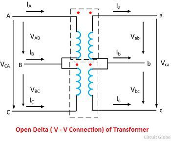
Open delta or V-V Connection
If one transformer of delta-delta connection is damaged or accidentally opened, then the defective transformer is removed, and the remaining transformer continues to work as a three phase bank. The rating of the transformer bank is reduced to 58% of that of the actual bank. This is known as the open delta or V-V delta. Thus, in open winding transformer, two transformers are used instead of three for the 3-phase operation.
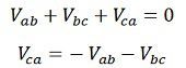
Let the Vab, Vbc and Vca be the voltage applied to the primary winding of the transformer. The voltage induced in the transformer secondary or on winding one is Vab. The voltage induced on the low voltage winding two is Vbc. There is no winding between points a and c. The voltage may be found by applying KVL around a closed path made up of point a, b, and c. Thus,
Let, 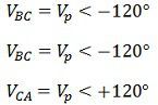
Where Vp is the magnitude of the line on the primary side.

On substituting the value of Vab and Vbc in equation, we get
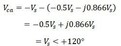
The Vca is equal in magnitude from the secondary terminal voltage and 120º apart in time from both of them. The balanced three phase line voltage produced balanced 3-phase voltage on the secondary side.
If the three transformers are connected in delta-delta configuration and are supplying rated load and if the connection becomes V-V transformer, the current in each phase winding is increased by √3 times. The full line current flows in each of the two phase windings of the transformer. Thus the each transformer in the V-V system is overloaded by 73.2%.
It should be noticed that the load should be reduced by √3 times in case of an open delta connected transformer. Otherwise, serious overheating and breakdown of the two transformers may take place.