Definition: The power factor meter measures the power factor of a transmission system. The power factor is the cosine of the angle between the voltage and current. The power factor meter determines the types of load using on the line, and it also calculates the losses occur on it.
The power factor of the transmission line is measured by dividing the product of voltage and current with the power. And the value of voltage current and power is easily determined by the voltmeter, ammeter and wattmeter respectively. This method gives high accuracy, but it takes time.
The power factor of the transmission line is continuously changed with time. Hence it is essential to take the quick reading. The power factor meter takes a direct reading, but it is less accurate. The reading obtained from the power factor meter is sufficient for many purposes to expect precision testing.
The power factor meter has the moving system called pointer which is in equilibrium with the two opposing forces. Thus, the pointer of the power factor meter remains at the same position which is occupied by it at the time of disconnection.
Types of Power Factor Meter
The power factor meter is of two types. They are
- Electrodynamometer
- Single Phase Electrodynammeter
- Three Phases Electrodynamometer
- Moving Iron Type Meter
- Rotating Iron Magnetic Field
- Number of Alternating Field
The different types of power factor meter are explained below in details.
Single Phase Electrodynamometer Power Factor Meter
The construction of the single phase electrodynamometer is shown in the figure below. The meter has fixed coil which acts as a current coil. This coil is split into two parts and carry the current under test. The magnetic field of the coil is directly proportional to the current flow through the coil.
The meter has two identical pressure coils A and B. Both the coils are pivoted on the spindle. The pressure coil A has no inductive resistance connected in series with the circuit, and the coil B has highly inductive coil connected in series with the circuit.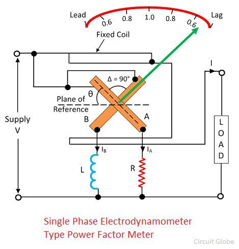 The current in the coil A is in phase with the circuit while the current in the coil B lag by the voltage nearly equal to 90º. The connection of the moving coil is made through silver or gold ligaments which minimize the controlling torque of the moving system.
The meter has two deflecting torque one acting on the coil A, and the other is on coil B. The windings are so arranged that they are opposite in directions. The pointer is in equilibrium when the torques are equal.
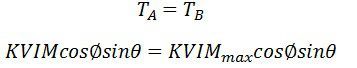
Deflecting torque acting on the coil A is given as![]() θ – angular deflection from the plane of reference.
θ – angular deflection from the plane of reference.
Mmax – maximum value of mutual inductance between the coils.
The deflecting torque acting on coil B is expressed as
![]()
![]() The deflecting torque is acting on the clockwise direction.
The deflecting torque is acting on the clockwise direction.
The value of maximum mutual inductance is same between both the deflecting equations.
 This torque acts on anti-clockwise direction. The above equation shows that the deflecting torque is equal to the phase angle of the circuit.
Three Phase Electrodynometer Power Factor Meter
The construction of the three phase meter is shown in the figure below. The electrodynamometer is only useful for the balanced load. The moving coil is placed at an angle of 120º. They are connected across different phases of the supply circuit. Both the coil has a series resistance.
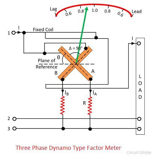 The voltage across the coil A is V12 and the current across it IA1. The circuit of the coil is resistive, and hence the current and voltage are in phase with each other. Similarly, the voltage V13 and the current IB1 is in phase with each other.
The phasor diagram of the three phase electrodynamic meter is shown in the figure below. 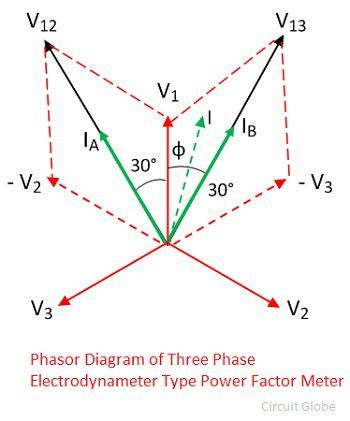 Let Φ – phase angle of the circuit.
θ – angular deflection from the plane of reference.
Torque acting on coil A is 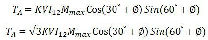 Torque acting on coil B is
 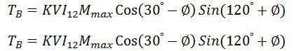 The torque TA and TB are acting on the opposite directions.
 ![]() Thus the angular deflection of the coil is directly proportional to the phase angle of the circuit.
Thus the angular deflection of the coil is directly proportional to the phase angle of the circuit.
Moving Iron Power Factor Meter
The moving iron instrument is divided into two categories. They are the rotating magnetic field to some alternating fields.
A. Rotating Field Power factor Meter – The following are the essential feature of the rotating magnetic field. The power factor meter has three fixed coils, and their axes are 120º displaced from each other. The axes are intersecting each other. The coils are connected to the three phase supply with the help of the current transformer.
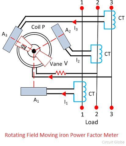 The P is the fixed coil connected in series with the high resistance circuit across the phases 2 and 3. There is an iron cylinder across coil P. The two iron vanes are fixed to the cylinder. The spindles also carry damping vanes and pointer.
The phasor diagram of the power factor meter is shown in the figure. 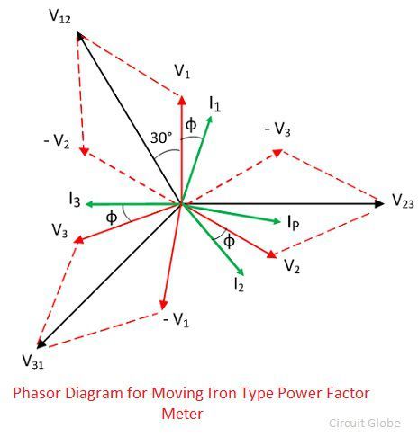 The total torque of the meter is zero for steady state deflection.
 The coil P and the iron cylinders generate the alternating flux which interacts with the flux of the fixed coils. The interaction of the coil generates the moving system which determined the phase angle of the current. The vanes of the power factor meter are magnetized by the current of the moving coil which is in phase with the system line voltage.
Advantages of Moving Iron power Power Factor
- The meter requires large working force as compared to the electrodynamometer type meter.
- The coils of the moving iron instruments are fixed permanently.
- The range of the scale extends up to 360º.
- The construction of the meter is robust and simple.
- The moving iron instrument is cheap as compared to electrodynamic meter.
Disadvantages of moving iron instrument
- The loss occurs in the iron part of the meter. The losses depend on the load and the frequency of the meter.
- The meter has low accuracy.
- The calibration of the meter is affected because of the variation in supply frequencies, voltage and waveforms etc.
The power factor meter is used for measuring the power factor of the balanced load.
I like it
It is very useful for the students.
A very nice technical briefings usable for a technical personnel working in the relevant field.
Well balanced content.
Awesome Notes
Far Better than some standard books