For variable speed applications, the DC motor drives are used in the past. But this motor has several disadvantages like the presence of commutator and brushes due to which frequent maintenance is required. This problem is overcome by the variable speed induction motor drive. The induction motor drive is cheaper, lighter, smaller, more efficient and requires low maintenance. The only disadvantage of an induction motor drive is its higher cost.
The induction motor drive has many applications like it is used in fans, blowers, mill run-out tables, cranes conveyers, traction, etc. The induction motor drive is self-starting, or we can say when the supply is given to the motor, it starts rotating without any external supply.
The initial resistance of the supply is zero, and hence large current flows through the motor, which damages the windings of the motor. For reducing the flow of starting current, the different starting methods are used. These methods keep the magnitude of starting current within a prescribed limit such that it does not cause the overheating.
Starting Methods
The methods employed for starting motors are:
- Star-delta starter
- Auto-transformer starter
- Reactor starter
- Saturable reactor starter
- Part windings starter
- AC voltage controller starter
- Rotor resistance starter for wound rotor motor
The starting methods are explained below in details.
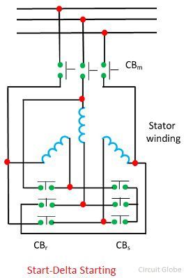
Star-Delta Starter
In this method, an induction motor designed to operate normally with delta connection is connected in a star during starting. Thus the stator voltage and current are reduced by 1/√3. The motor torque is proportional to stator terminal voltage, starting torque is reduced to one-third.
A circuit diagram for a star-delta starter is shown in the figure below. The circuit breaker CBm and CBs are closed to start the machine with star connection. When the steady state speed is reached, CBs is opened, and CBr is closed to connect the machine in Delta.
 Auto-Transformer Starter
In this method, the starting current and motor terminal voltage are reduced by an autotransformer. The torque is proportional to the square of the motor terminal voltage, and hence it is also reduced. When the motor reaches its steady states, it is connected to the full supply voltage. An auto-transformer starter is shown in the figure below.
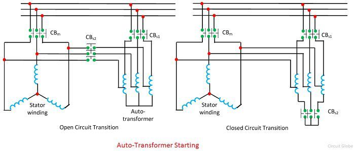 In the starting, the CBs1 and CBs2 are closed, and CBm is open. When the motor accelerates at its full speed, the CBs2 is opened, and CBm closed. Now CB1 is opened to disconnect auto-transformer from the supply.
Reactor Starter
The starting current is reduced by connecting the three phase reactor in series with the starter. When the motor reaches its steady state, the reactor is removed from the circuit. The reactor starter circuit is shown in the figure below.
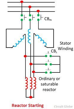 The circuit breaker CBs is closed to start the machine. When the motor reaches its full speed, the CBs is closed to introduce the reactor at the neutral end of the stator winding. Thus, the starting current of the motor is reduced to its minimum value.
Saturable Starter Reactor
The saturable reactor is introduced in series with the stator, and it gives the soft start to the motor. The saturable reactor has DC control winding which controlled the torque of the motor steplessly. The reactance of the saturable reactance can be varied steplessly by changing the control winding current.
In the starting, the reactance is set at the higher value, and hence the starting torque is close to zero. The reactance is controlled smoothly by increasing the winding control current, and this gives the step less variation of starting torque. Thus motor starts without any jerks and accelerates smoothly.
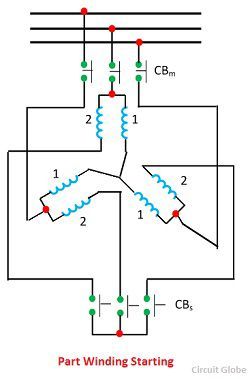
Part Winding Starting
Some squirrel cage motors have two or more stator windings, and these windings are connected in parallel during the normal operation. During starting only one winding is connected, which increases the starter impedance and reduces the starting current. This starting scheme is called part winding starting. The machine starts with winding 1 when the CBm is closed and after the full speed is reached the CBs is closed to connect winding 2.
 Rotor Resistance Starter
This method connects the rotor resistance in the external circuit. The highest value of current is chosen to limit the current at zero speed within the safe value. The rotor resistance starter is shown in the figure below.
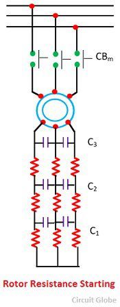 As the motor accelerates the external resistance are cut one by one by closing contacts and hence the rotor current is limited between specified maximum and minimum value.