The current limiting reactor is an inductive coil having a large inductive reactances in comparison to their resistance and is used for limiting short circuit currents during fault conditions. Current-voltage reactors also reduced the voltage disturbances on the rest of the system. It is installed in feeders and ties, in generators leads, and between bus sections, for reducing the magnitude of short circuit currents and the effect of the respective voltage disturbance.
Current reactor allows free interchange of power under normal condition, but when the fault occurs the disturbance is restricted by the current reactor to the faulty section. As the resistance of the system is very small as compared to their reactance. Hence, the efficiency of the system is not much affected.
Main Function of Current Limiting Reactor
The main purpose of the current limiting reactor is that its reactance should not decrease when a large short current flows through its windings. When the fault current exceeds about three times rated full-load current then large cross section iron cored reactor is used for limiting the fault current. Because of the large cross-section area, the iron cored reactor becomes very costly and heavy. Therefore, the air cored reactor is usually used to limit the short circuit or fault current.
The iron-cored reactor produces hysteresis and eddy current loss due to which more power is consumed as compared to air cored reactor. Normally, in an air cored reactor, the total losses are of the order of 5% of KVA rating of the reactor.
Functions of Current Limiting Reactor
- Current limiting reactor reduces the flow of short circuit current so as to protect the appliances from mechanical stress and overheating.
- Current reactor reduced the magnitude of voltage disturbances which is caused by short circuits.
- It limits the fault current to flow into the healthy feeders or parts of the system, thereby avoiding the fault from spreading. This increase the chances of continuity of supply.
Drawbacks of current limiting reactor
The main drawbacks of the current limiting reactors are as follows
- When the reactor is installed on the network, the total percentage reactance of the circuit increases.
- It decreases the power factor and thus the regulation becomes poorer.
Location of Reactors
Reactors are located at different location in a power system for reducing the short circuit current. These reactors may be connected in series with the generators, feeders or in bus-bars as explained below.
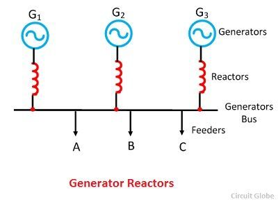
Generators Reactors
Generator reactors are inserted between the generator and the generator bus. Such reactors protect the machines individually. In power station generator, reactors are installed along with the generators. The magnitude of reactors is approximately about 0.05 per unit. The main disadvantages of such type of reactors are that if the fault occurs on one feeder, then the whole of the system will be adversely affected by it.
 Feeders Reactors
Reactors, which is connected in series with the feeder is called feeders reactor. When the fault occurs on any one feeder, then the voltage drops occur only in its reactors and the bus bar is not affected much. Hence the machines continue to supply the load. The other advantage is that the fault occurs on a feeder will not affect the others feeders, and thus the effects of fault are localized.
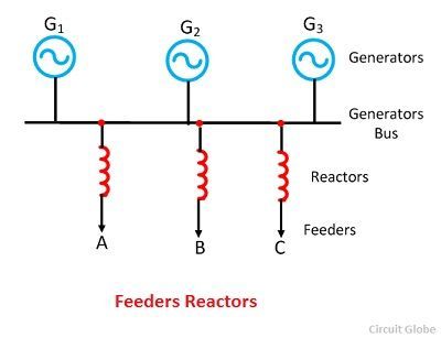 The disadvantage of such type of reactors is that it does not provide any protection to the generators against short circuit faults occurs across the bus bars. Also, there is a constant voltage drop and constant power loss in reactors during normal operating conditions.
Bus-Bar Reactor
When the reactors are inserted in the bus bar, then it is called bus-bar reactors. The constant voltage drop and constant power loss in reactors may be avoided by inserting the reactors in the bus bars. The bus bar reactor for ring system and the tie system are explained below.
Bus-Bar Reactors (Ring System)
Bus-bar reactors are used to tie together the separate bus sections. In this system sections are made of generators and feeders and these sections are connected to each other to a common bus bar. In such type of system normally one feeder is fed from one generator. In normal operating conditions a small amount of power flows through the reactors. Therefore voltage drop and the power loss in the reactor is low. The bus bar reactor, therefore, made with high ohmic resistance so that there is not much voltage drop across it.
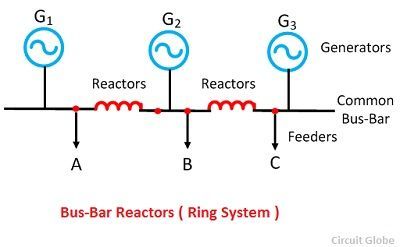 When the fault occurs on any one feeders, only one generator feeds the fault while the current of the other generator is limited because of the presence of the bus-bar reactors. The heavy current and voltage disturbances caused by a short circuit on a bus section are reduced and restricted to that faulty section only. The only drawback of such type of reactor is that it does not protect the generators connected to the faulty sections.
Bus-bar Reactors (Tie-Bus System)
This is the modification of the above system. In tie-bus system, the generator is connected to the common bus-bar through the reactors, and the feeder is fed from generator side.
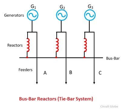 The operation of the system is similar to the ring system, but it has got additional advantages.In this system, if the number of sections is increased, the fault current will not exceed a certain value, which is fixed by the size of the individual reactors.