Definition: The voltage source inverter is defined as the inverter which takes a variable frequency from a DC supply. The input voltage of the voltage source inverter remains constant, and their output voltage is independent of the load.The magnitude of the load current depends on the nature of the load impedance.
The figure below shows a voltage source inverter employing transistor.
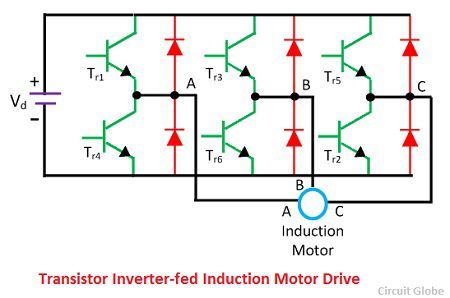
The voltage source inverter use self-commutated device like MOSFET, IGBT, GTO, etc. It is operated as a stepped-wave inverter or a pulse width modulation. When the voltage source inverter is operated as a stepped-wave inverter, then the transistor is switched in the sequence of their number with a time difference of T/6.
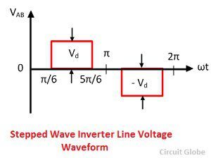
The each of the transistors is kept on for the duration of T/2, where T is the period for one cycle. The waveform of the line voltage is shown in the figure below. The frequency of the inverter is varied by varying T, and the output voltage of the inverter is varied by varying DC input voltage.
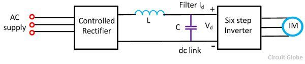
When the supply is DC, then the variable DC input is obtained by connecting a chopper between DC supply and inverter.
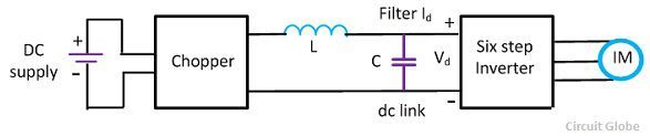
When the supply is AC, then the DC input voltage is obtained by connecting the controlled rectifier between the AC supply and inverter shown in the figure below.The capacitor C filter out the harmonics in DC link voltage.
The main drawback of the VSI induction motor drive is the large harmonics of the low frequency in the output voltage. The harmonics increases the loss in the motor and cause the jerky motion of the rotor at low speed.
Braking of VSI Induction Motor Drives
Dynamic Braking: In dynamic braking, the switch SW and a self-commutated switch in series with the braking resistance R are connected across the DC links. When the operation of the motor is shifted from motoring to braking switch SW is opened. The energy flowing through the DC link charges the capacitors and its voltage rises.
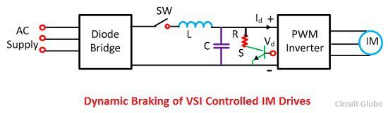
When the voltage crosses the set value, switch S is closed, connecting the resistance across the link. The energy which is stored in the capacitor flows into the resistance and reduces the DC link voltage. When it falls to its nominal value S is opened.Thus the closing and opening of the switch depends on the DC link voltage, and the generated energy is dissipated in the resistance gives dynamic braking.
Regenerative Braking: Let us consider the regenerative braking of pulse width modulation of inverter drive. When the operation shift from motoring to braking, the DC link current Id reverse and flows into the DC supply feeding the energy to the source.Thus the drive already has the regenerative braking capability.
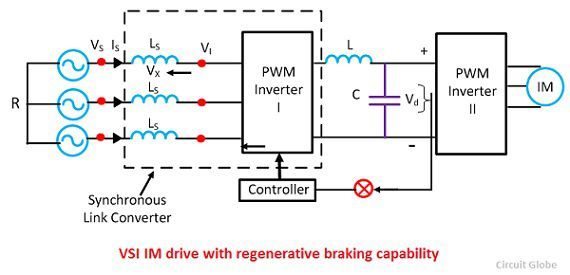
In regenerative braking the, the power supply to the DC link must be transferred to the AC supply. When the operation shift from motoring to braking, the DC link current Id reverse, but the Vd remain in the same direction. Thus, for regenerative braking, a converter is required for converting the DC voltage and direct current in either direction.
Four Quadrant Operation
Braking capability obtains the four quadrant operation of the drive. The reduction of the inverter frequency makes the synchronous speed less than the motor speed. Thus the operation of the motors is transferred from quadrant 1 (forward motoring) to quadrant 2 (forward braking).
The inverter frequency and voltage are progressively reduced as the speed falls, to brake the machine from zero speed. The phase sequence of the output voltage is reversed by interchanging the firing pulse of the thyristor. Thus, the operation of the motor is transferred from the second quadrant to the third quadrant (reverse motoring). The inverter frequency and voltage are increased to get the required speed in the reverse direction.