Definition: The instrument used for measuring the resistance of the earth is known as earth tester. All the equipment of the power system is connected to the earth through the earth electrode. The earth protects the equipment and personnel from the fault current. The resistance of the earth is very low. The fault current through the earth electrode passes to the earth. Thus, protects the system from damage.
The earth electrodes control the high potential of the equipment which is caused by the high lightning surges and the voltage spikes. The neutral of the three-phase circuit is also connected to the earth electrodes for their protection.
Before providing the earthing to the equipment, it is essential to determine the resistance of that particular area from where the earthen pit can be dug. The earth should have low resistance so that the fault current easily passes to the earth. The resistance of the earth is determined by the help of earth tester instrument.
Construction of Earth Tester
The earth tester uses the hand driven generator. The rotational current reverser and the rectifier are the two main parts of the earth tester. The current reverser and the rectifier are mounted on the shaft of the DC generator. The earth tester works only on the DC because of the rectifier.
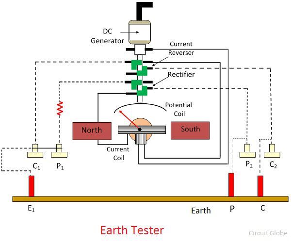
The tester has two commutators place along with the current reverser and rectifier. The each commutator consist four fixed brushes. The commutator is a device used for converting the direction of flows of current. It is connected in series with the armature of the generator. And the brushes are used for transferring the power from the stationary parts to the moving parts of the devices.
The arrangement of the brushes can be done in such a way that they are alternately connected with one of the segments even after the rotation of the commutator. The brushes and the commutators are always connected to each other.
The earth tester consists two pressures and the current coils. The each coil has two terminals. The pair of the pressure coil and the current coil are placed across the permanent magnet. The one pair of current and pressure coil is short-circuited, and it is connected to the auxiliary electrodes.
The one end terminal of the pressure coil is connected to the rectifier, and their other end is connected to the earth electrode. Similarly, the current coil is connected to the rectifier and earth electrode.
The earth tester consists the potential coil which is directly connected to the DC generator. The potential coil is placed between the permanent magnet. The coil is connected to the pointer, and the pointer is fixed on the calibrated scale. The pointer indicates the magnitude of the earth resistance. The deflection of the pointer depends on the ratio of the voltage of pressure coil to the current of the current coil.
The short-circuit current passes through the equipment to the earth is alternating in nature. Thus, we can say that the alternating current flows in the soil. This alternative current reduces the unwanted effect of the soil, which occurs because of chemical action or because of the production of back emf.
Very helpful
Fabulous and very helpful .
I learn everything thing about earth tester
Good work
Keep it up…..