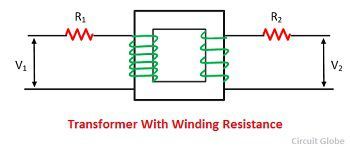
The ideal transformer has no resistance, but in the actual transformer, there is always some resistance to the primary and secondary windings. For making the calculation easy the resistance of the transformer can be transferred to the either side. The resistance is transferred from one side to another in such a manner that the percentage of voltage drop remains the same when represented on the either side. These resistances are shown external to the windings in the figure below.
Let the primary resistance R1 be transferred to the secondary side, and the new value of this resistance be R’1. The R’1 is called the equivalent resistance of primary referred to secondary side as shown in the figure below. I1 and I2 are the full loads primary and secondary current respectively.
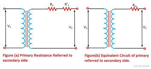
Then,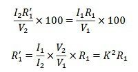
Total equivalent resistance referred to secondary,
![]()
Now consider resistance R2, when it is transferred to primary, the value of the new resistance is R’2. The R’2 is called the equivalent resistance of the of secondary referred to as primary as shown in the figure below.
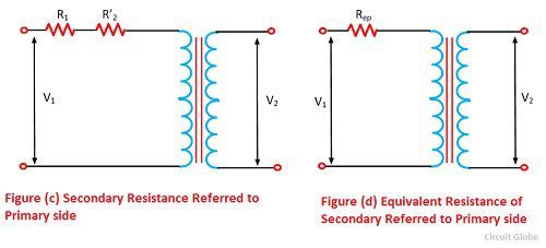
Then,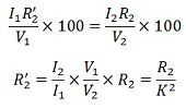
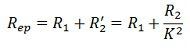
Total equivalent resistance referred to primary,
 If the winding of the transformer is connected in star then their resistance will be measured between the neutral and line.
how to calculate transformation ratio using only winding resistance.
good illustration