Definition: The transformer which is free from all types of losses is known as an ideal transformer. It is an imaginary transformer that has no core loss, no ohmic resistance, and no leakage flux. The ideal transformer has the following important characteristic.
- The resistance of their primary and secondary winding becomes zero.
- The core of the ideal transformer has infinite permeability. The infinite permeable means less magnetizing current requires for magnetizing their core.
- The leakage flux of the transformer becomes zero, i.e. the whole of the flux induces in the core of the transformer links with their primary and secondary winding.
- The ideal transformer has 100 percent efficiency, i.e., the transformer is free from hysteresis and eddy current loss.
The above mention properties are not possible in the practical transformer. In an ideal transformer, there is no power loss. Therefore, the output power is equal to the input power.
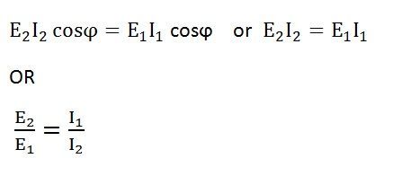 Since El ∞ N2 and E1 ∞ N1, also E1 is similar to V1 and E2 is similar to V2
Therefore, the transformation ratio will be given by the equation shown below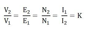 The primary and the secondary currents are inversely proportional to their respective turns.
Behavior of Ideal Transformer
Consider the ideal transformer shown in the figure below: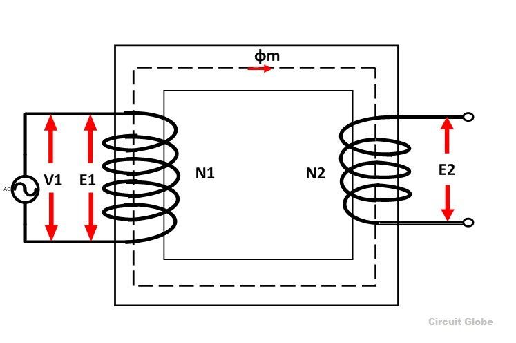
The voltage source V1 is applied across the primary winding of the transformer. Their secondary winding is kept open. The N1 and N2 are the numbers of turns of their primary and secondary winding.
The current Im is the magnetizing current flows through the primary winding of the transformer. The magnetizing current produces the flux φm in the core of the transformer.
As the permeability of the core is infinite the flux of the core link with both the primary and secondary winding of the transformer.
The flux link with the primary winding induces the emf E1 because of self-induction. The direction of the induced emf is inversely proportional to the applied voltage V1. The emf E2 induces in the secondary winding of the transformer because of mutual induction.
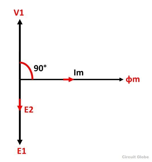
Phasor Diagram of Ideal Transformer
The phasor diagram of the ideal transformer is shown in the figure below. As the coil of the primary transformer is purely inductive the magnetizing current induces in the transformer lag 90º by the input voltage V1.
The E1 and E2 are the emf induced in the primary and secondary winding of the transformer. The direction of the induced emf inversely proportional to the applied voltage.
Point to Remember
The input energy of the transformer is equal to its output energy. The power loss in the ideal transformer becomes zero.
it is compiled in a good format.
it’s nice to memorize and to study.
THANK YOU
Can you explain it for me the point you written there that is (the direction of induced emf is inversely proportional to the applied voltage) How and why it’s direction is opposite ??
because of lenz law