The winding factor is the method of improving the rms generated voltage in a three-phase AC machine so that the torque and the output voltage do not consist of any harmonics which reduces the efficiency of the machine. Winding Factor is defined as the product of the Distribution factor (Kd) and the coil span factor (Kc). The distribution factor measured the resultant voltage of the distributed winding regards concentrate winding and the coil span is the measure of the number of armature slots between the two sides of a coil. It is denoted by Kw. The EMF equation is given below: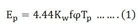
It is assumed that the induced voltage is sinusoidal. However, if the flux density distribution is non-sinusoidal, the induced voltage in the winding will be non-sinusoidal. The coil span factor, distribution factor, and winding factor will be different for each harmonic voltage. From equation (1), the fundamental EMF per phase is given by the equation shown below:![]()
The third harmonic, EMF per phase will be: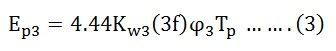
The nth harmonic, EMF per phase will be here subscript 1,3 and n denote fundamental, third, and nth harmonics respectively.
Therefore,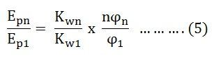 Where,
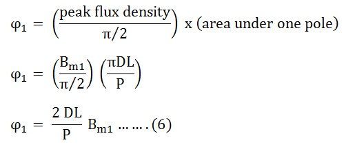
- ϕ1 is the total fundamental flux per pole.
- ϕ1 = average flux density x area under one pole
 Where,
- Bm1 is the peak value of the fundamental component of the flux density wave
- D is the diameter of the armature or the mean air gap diameter
- L is the axial length of the armature or the active coil side length
Similarly for the nth harmonic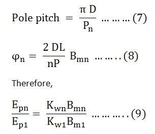
Where,
Bmn is the peak value of the nth harmonic flux density
Winding Factor for nth Harmonic
The winding factor corresponding to the nth harmonic voltage is given as: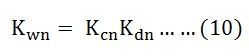
Where Kcn and Kdn are the coil span factor and distribution factor for the nth harmonic.
Therefore, the nth order harmonic induced EMF per phase is given by the equation shown below: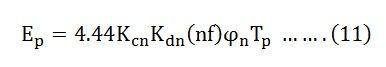
Where,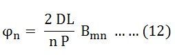
In addition, to the fundamental flux, the induced voltage in a winding will contain harmonics because of the non-sinusoidal space flux density distribution. Since the positive and the negative halves of the flux density wave are identical, only odd harmonics can be present, and even harmonics are absent. Therefore, phase voltage may contain third, fifth, seventh, and higher-order harmonics.
Mainly the three-phase alternators are star-connected. The third-order harmonic voltages of all the phases are equal in-phase and magnitude. The phase of the star-connected machine is such that the voltage across any two lines is the phasor difference in the voltages of the corresponding phases. Hence, the third harmonic or multiple of the third harmonic are absent in the line voltage of the star-connected synchronous machine.
Since the strength of the harmonic components of voltage decreases with the increasing frequency, only fifth and seventh harmonics are important. These are known as Belt Harmonics.
Thus, the root mean square voltage of the induced voltage across lines of a 3 phase, star connected machine is given by the equation shown below: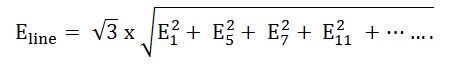
Where, subscripts 1, 5, 7, 11 ….. denotes fundamental fifth, seventh, eleventh harmonics respectively.