The Resistance of the transformer is defined as the internal resistance of both primary and secondary windings. In an actual transformer, the primary and the secondary windings have some resistance represented by R1 and R2 and the reactances by X1 and X2. Let K be the transformation ratio.
To make the calculations easy the resistances and reactances can be transferred to either side, which means either all the primary terms are referred to the secondary side, or all the secondary terms are referred to the primary side.
The resistive and the reactive drops in the primary and secondary side are represented as follows
- Resistive drop in the secondary side = I2R2
- Reactive drop in the secondary side = I2X2
- Resistive drop in the primary side = I1R1
- Reactive drop in the primary side = I1X1
Primary Side Referred to Secondary Side
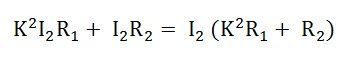
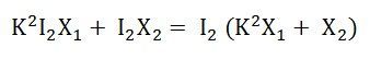
Since the transformation ratio is K, the primary resistive and reactive drop as referred to secondary side will be K times, i.e., K I1R1 and K I1X1 respectively. If I1 is substituted equal to KI2 then we have primary resistive, and reactive drop referred to secondary side equal to K2I2R1 and K2I2X1 respectively.
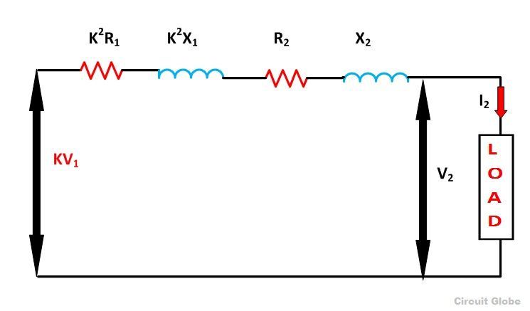
The total resistive drop in a transformer
The total reactive drop in a transformer
The terms
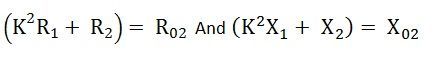
![]() represent the equivalent resistance and reactance of the transformer referred to the secondary side.
represent the equivalent resistance and reactance of the transformer referred to the secondary side.
Where
 Thus,
Thus,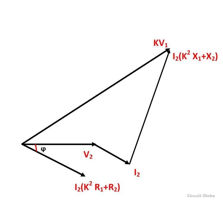
From the phasor diagram shown above the equation can be formed as
 Where V2 is the secondary terminal voltage and I2 is secondary current lagging behind the terminal voltage V2 by an angle ϕ.
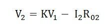
Since the term
![]() is very small and is neglected as compared to the term
is very small and is neglected as compared to the term ![]()
Now the equation becomes
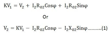
Where V1 is the applied voltage to the primary winding
If the load on the secondary side of the transformer is purely resistive then ϕ = 0 and the equation (1) becomes
 If the load on the secondary side of the transformer is capacitive then ϕ should be taken as negative, and the equation (1) becomes
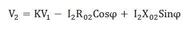
Therefore this will be the load voltage.