Definition: The sequence impedance network is defined as a balance equivalent network for the balance power system under an imagined working condition so that only single sequence component of voltage and current is present in the system. The symmetrical components are useful for computing the unsymmetrical fault at different points of a power system network. The positive sequence network determines the load flow studies in power system.
Every power system has three sequence network (positive, negative and zero sequence networks) and these networks carrying three sequence current. These sequence currents interconnect in different ways to represent a different unbalance fault condition. These sequence current and voltage are calculated during the fault due to which actual current and voltage can be determined.
The positive network is considered in the analysis of symmetrical fault. The positive sequence network is the same as that of the sequence reactance or impedance network. The negative sequence network is similar to the positive sequence network only difference is that the negative sequence network is of opposite sign to that of the positive sequence impedance. The zero sequence network will be internally free of the internal fault point and the flow of current being caused by the voltage at the fault point.
Sequence Network For Fault Calculation
The fault in the power system means the system is put into an unbalanced state of operation. The unbalanced position of the power system is replaced by the balanced, positive set and a symmetrical balanced negative sequence set and a single phase zero sequence set. When the fault occurs in the system, it is considered that the three sequence set is injected into the system. The post fault voltage and current are determined by the response of the system of each component set.
For determining the response of the system three sequence component is used. Considered that the each sequence network is replaced by the Thevenin’s equivalent circuit between two points. The each sequence network can be reduced to a single voltage and single impedance shown in the figure below. The sequence network is represented by the box in which the one point is the fault point, and the other is the zero potential of the reference bus N.
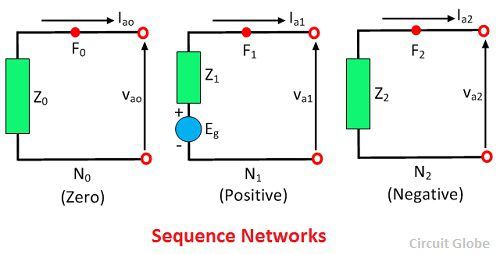
For positive sequence network, the Thevenin voltage is the open circuit voltage VF at point F. The voltage Vf is the pre-fault voltage in phase a, at the fault point F. The Eg also represents it. Thevenin voltage in negative and zero sequence networks are zero because the negative and zero sequences voltage at the fault point are zero in the balanced system.
The current Ia flows from the system into the fault, thus its component Ia0, Ia1, and Ia2 flow away from the fault point F. The symmetrical component of the voltage at the fault point may be written as
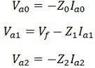 Where Z0, Z1 and the Z2 are the total equivalent impedance of the zero, positive and negative sequence network up to the fault point.
This website is best for understanding purpose because all the sentences are easy which had been used in this site.