Definition: The instrument uses for determining the sequence of the three-phase system is known as the phase sequence indicator. The change in the sequence of the power supply changes the direction of rotation of the machine. Because of which the entire supply system will be affected. For proper connection, it is essential to know the sequence of the phases which can be done by the use of the phase sequence indicator.
What is Phase Sequence?
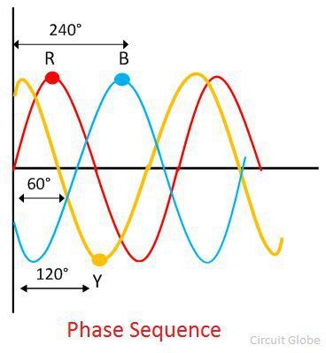
The phase sequence is the order of the phases in which the polyphase system attains their maximum value. Consider the R, Y and B are the three phases of the supply system. The phase angle between the three phases can determine by dividing the total number of phases by the 360°. In three phase system, the phases are split by an angle of 120°.
The waveforms for the three phases is shown in the figure below.
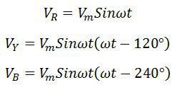
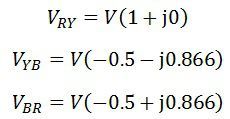
The below-given equations represent the value of each phase.
 Types of Phase Sequence Indicator
The phase sequence indicator is of two types. They are
- Rotating Type
- Static Type
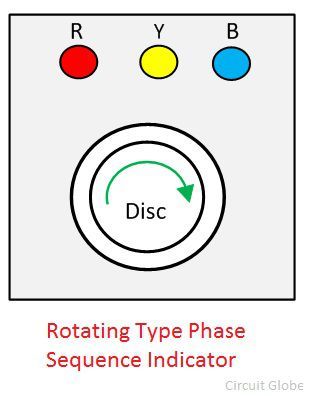
Rotating Type Phase Sequence Indicators
The rotating type phase sequence indicators show the direction of the phase sequence by rotating the disc placed at the centre of the instrument. It has three terminals which are connected to the terminals of the measurand devices.
The working principle of the rotating phase sequence indicator is similar to that of the induction motor. The coils of the induction motor are star connected. The phase sequence of the power supply is RYB. When the supply is given to the motor coils, rotating magnetic fields induce in the coils. This rotating magnetic field induces the eddy EMF in the aluminium disc.
 The eddy EMF causes the eddy current in the disc. The interaction of the eddy current and the rotating magnetic field produces the torque because of which the disc starts rotating.
The direction of the disc shows the phase sequence of the supply system. If the disc rotates in the clockwise direction, the phase sequence is RYB. The anticlockwise direction of the aluminium disc is because of the reverse phase sequence.
Static Type Phase Sequence Indicator
The static phase sequence indicators consist two lamps and an inductor. The device whose phase sequence is used to be known is connected to the static phase sequence indicators. If the lamp 1 is dim and the lamp 2 glows brightly, then the phase sequence of supply is RYB.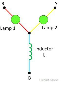 If the lamp 1 glows brightly and the lamp 2 is dim, the device has reverse phase sequence. The brightness of the lamp depends on the voltage drops occurs across it. The working of the static phase sequence supply can more easily be understood with the help of the following analysis.
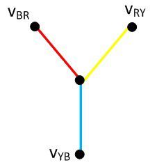
Let the phase sequence of the supply is RYB, and the relationship of the phase concerning the voltage is VRY, VBY and VRB as shown in the figure below.
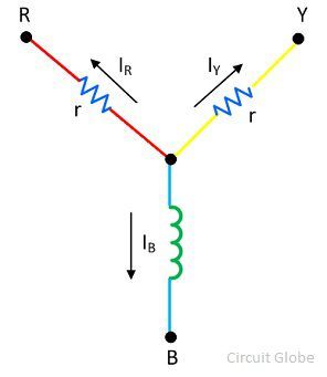
 The equation gives the value of current
![]() On solving the above equations by the help of the images we see that the voltage drop across the lamp 1 is 27% and that of the lamp 2 is IY = 0.27 Ir. Thereby, the lamp 1 is dim, and lamp 2 glows brightly.
On solving the above equations by the help of the images we see that the voltage drop across the lamp 1 is 27% and that of the lamp 2 is IY = 0.27 Ir. Thereby, the lamp 1 is dim, and lamp 2 glows brightly.
The neon lamp along with the resistance and the capacitor is also used in the phase sequence indicators.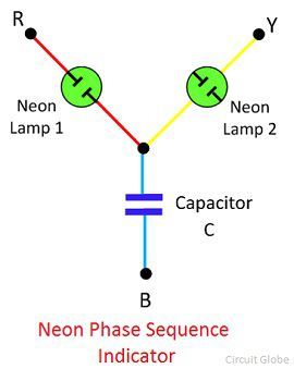 The resistance is connected in series with the neon lamp for limiting the value of current.
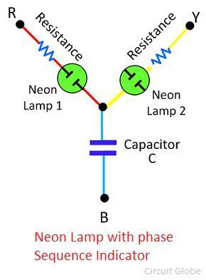 If the phase sequence of the supply is RYB, the Lamp A will glow, and the lamp B will not glow. And for the reverse phase sequence, the lamp A will be darker, and B will glow.
Please let me know what is the value of capacitor and resistance
Thanks