Definition: The instrument which measures the storage factor or quality factor of the electrical circuit at radio frequencies, such type of device is known as the Q-meter. The quality factor is one of the parameters of the oscillatory system, which shows the relation between the storage and dissipated energy.
The Q meter measures the quality factor of the circuit which shows the total energy dissipated by it. It also explains the properties of the coil and capacitor. The Q meter uses in a laboratory for testing the radio frequency of the coils.
Working Principle of Q meter
The Q meter works on series resonant. The resonance is the condition exists in the circuit when their inductance and capacitance reactance are of equal magnitude. They induce energy which is oscillating between the electric and magnetic field of the capacitor and inductor respectively.
The Q-meter is based on the characteristic of the resistance, inductance and capacitance of the resonant series circuit. The figure below shows a coil of resistance, inductance and capacitance connected in series with the circuit.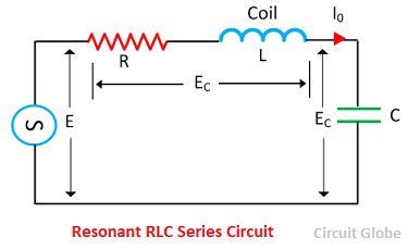 At resonant frequency f0,
 ![]() The value of capacitance reactance is
The value of capacitance reactance is 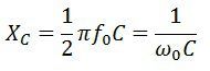 At inductive reactance,
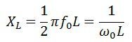
At the resonant frequency, 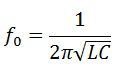 and current at resonance becomes
  The phasor diagram of the resonance is shown in the figure
 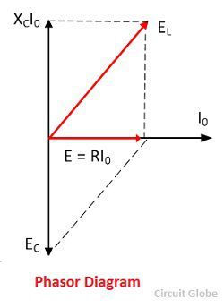 The voltage across the capacitor is expressed as
 ![]() Input voltage
Input voltage ![]()
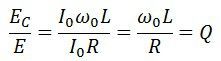
![]() The above equation shows that the input voltage E is Q times the voltage appears across the capacitor. The voltmeter is calibrated for finding the value of Q factor.
The above equation shows that the input voltage E is Q times the voltage appears across the capacitor. The voltmeter is calibrated for finding the value of Q factor.
Applications of the Q-meter
The following are the applications of the Q-meter.
1. Measurement of Q – The circuit used for measurement of Q is shown in the figure. 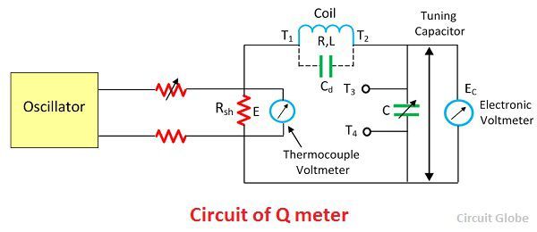
The oscillator and tuning capacitor adjust to the desired frequency for obtaining the maximum value of E0. Under this condition, the value of the quality factor is expressed as True value is given as
 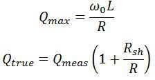 The value of the quality factor is obtained by the voltmeter which is connected across the capacitor. The measured value is the Q factor of the whole circuit and not only of the coil. Thus, errors occur in the reading because of the shunt resistance and distributed capacitance.
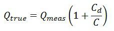 The above equations show that the measured value of the Q is smaller than the true value.
2. Measurement of Inductance – The inductance is measured by the equation shown below.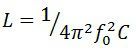 The value of f0 & C is required for calculating the value of inductance.
3. Measurement of Effective resistance – The equation computes the value of effective resistance
4. Measurement of Self-Capacitance – The self-capacitance is determined by measuring the two capacitance at different frequencies. The capacitor is adjusted to the high value, and the circuit is resonated by adjusting the oscillator frequency. The resonance of the circuit is determined by the Q meter.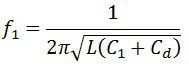 Thus,
Thus, 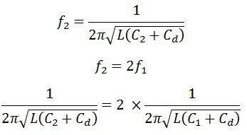 or distributed capacitance
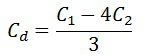
5. Measurement of Bandwidth – The equation below calculates the bandwidth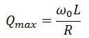
6. Measurement of Capacitance – The capacitance is determined by connecting the dummy coil across the terminal T1 and T2. Let the capacitor under test is connected across the terminal T3 and T4. The circuit is again resonated by varying the value of tuning capacitor C2. The value of testing capacitance is determined by subtracting the C1 and C2.
Q factor also measure properties of coils?
Yes, the Q-meter measures the electrical properties of both the inductive and non-inductive coils.
Is the LCR meter and Grip deep meter is also a type of Q meter?
is q meter is use to measure low impedence
How is q meter used to measure the inductance of a coil ?