Definition: The Weston frequency meter is a moving iron instrument used for measuring the unknown frequency of a signal. The frequency meter consists one inductive and one resistive coil. When the frequency of the signal varies from standard frequency, the current distribution across the coils becomes changes.
Working Principle of Weston Frequency Meter
The Weston frequency meter works on the principle that whenever the frequency of the measurand signal varies, the distribution of current between the inductive and the resistive circuit of the meter changes.
In other words, the change in frequency causes the change in the inductive impedance of the circuit because of which the variation occurs in the distribution of current between the parallel paths.
Note: The inductive impedance is the opposition offered by the circuit in the flow of current whenever the voltage applied to the circuit.
Construction of Weston Frequency Meter
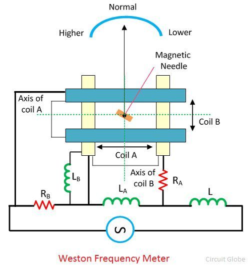
The meter consists two coils which are placed perpendicular to each other. The resistor RA is connected in series with the coil A and the inductor LB is connected in series with the coil B. The inductor LA is connected in parallel with the coil A and the resistance RB is in parallel with the coil B.
The meter has the soft iron pointer and magnetic needle which are mounted at the centre of the coils. The inductor L is connected in series with the LA and RB. The L reduces the harmonics present in circuit current. Thereby, reduces the error of the instrument.
Working of Weston Frequency Meter
The circuit diagram of the Weston frequency meter is shown in the figure below.
 When the supply is given to the Weston frequency meter, the current starts flowing into the coil A and B. The perpendicular magnetic field set up in the coils because of the current. The magnitude of the field depends on the current passes through the coils.
The magnetic field of both the coil A and coil B acts on the soft iron and the magnetic needle. The position of the needle depends on the relative magnitude of the magnetic field acts on it.
When the supply of normal frequency applies across the meter, the voltage drop of the same magnitude occurs across the reactance LA and resistance RB. Hence equal current passes through the coil A and coil B.
The meter designs such a way that when the normal frequency passes through the coil then the voltage drops across the LA, LB, RA, and RB remains same. Thus, same magnitude current passes through the coils. In this situation, the magnetic needle makes an angle of 45° concerning the coils and the soft iron needle places at the centre of the scale.
When the high frequency passes through the meter, the reactance LA and LB of the coil increases and the RA and RB remains same. The inductance increase the impedance of the coil A. The impedance means the opposition offered by the circuit in the flow of current. As the magnitude of current in the coil A decreases, the field develops because of the coil, A current also decreases.
The more current flows through the coil B because of the parallel connections with coil A. The magnetic field develops in the coil B becomes stronger than the coil A. The magnetic needles align themselves parallel to the axis of the strong magnetic field, and the pointer deflects towards the coil B or strong magnetic field.
When the frequency of the measurand signal reduces from the normal value, the opposite action takes place, and the pointer deflects towards the left.
Thank you so much i needed this info exam so urgently!!!!thank you once again!!
Thank you sir for easy sentence formations
thankyou so much for your support…
I am visiting this site frequently
This site has provided us the more relevant matter from the exam point of view
Loved this a lot
Thank you so much
This website is very useful for engineering students. Thank you so much! We can make notes easily from here.