Definition: The meter which is used for measuring the energy utilises by the electric load is known as the energy meter. The energy is the total power consumed and utilised by the load at a particular interval of time. It is used in domestic and industrial AC circuit for measuring the power consumption. The meter is less expensive and accurate.
Construction of Energy Meter
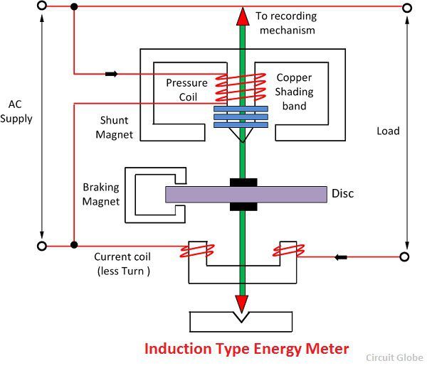
The construction of the single phase energy meter is shown in the figure below.
The energy meter has four main parts. They are the
- Driving System
- Moving System
- Braking System
- Registering System
The detail explanation of their parts is written below.
1. Driving System – The electromagnet is the main component of the driving system. It is the temporary magnet which is excited by the current flow through their coil. The core of the electromagnet is made up of silicon steel lamination. The driving system has two electromagnets. The upper one is called the shunt electromagnet, and the lower one is called series electromagnet.
The series electromagnet is excited by the load current flow through the current coil. The coil of the shunt electromagnet is directly connected with the supply and hence carry the current proportional to the shunt voltage. This coil is called the pressure coil.
The centre limb of the magnet has the copper band. These bands are adjustable. The main function of the copper band is to align the flux produced by the shunt magnet in such a way that it is exactly perpendicular to the supplied voltage.
2. Moving System – The moving system is the aluminium disc mounted on the shaft of the alloy. The disc is placed in the air gap of the two electromagnets. The eddy current is induced in the disc because of the change of the magnetic field. This eddy current is cut by the magnetic flux. The interaction of the flux and the disc induces the deflecting torque.
When the devices consume power, the aluminium disc starts rotating, and after some number of rotations, the disc displays the unit used by the load. The number of rotations of the disc is counted at particular interval of time. The disc measured the power consumption in kilowatt hours.
3. Braking system – The permanent magnet is used for reducing the rotation of the aluminium disc. The aluminium disc induces the eddy current because of their rotation. The eddy current cut the magnetic flux of the permanent magnet and hence produces the braking torque.
This braking torque opposes the movement of the disc, thus reduces their speed. The permanent magnet is adjustable due to which the braking torque is also adjusted by shifting the magnet to the other radial position.
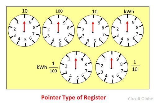
4. Registration (Counting Mechanism) – The main function of the registration or counting mechanism is to record the number of rotations of the aluminium disc. Their rotation is directly proportional to the energy consumed by the loads in the kilowatt hour.
The rotation of the disc is transmitted to the pointers of the different dial for recording the different readings. The reading in kWh is obtained by multiply the number of rotations of the disc with the meter constant. The figure of the dial is shown below.
Working of the Energy Meter
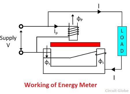
The energy meter has the aluminium disc whose rotation determines the power consumption of the load. The disc is placed between the air gap of the series and shunt electromagnet. The shunt magnet has the pressure coil, and the series magnet has the current coil.
The pressure coil creates the magnetic field because of the supply voltage, and the current coil produces it because of the current.
The field induces by the voltage coil is lagging by 90º on the magnetic field of the current coil because of which eddy current induced in the disc. The interaction of the eddy current and the magnetic field causes torque, which exerts a force on the disc. Thus, the disc starts rotating.
The force on the disc is proportional to the current and voltage of the coil. The permanent magnet controls Their rotation. The permanent magnet opposes the movement of the disc and equalises it on the power consumption. The cyclometer counts the rotation of the disc.
Theory of Energy Meter
The pressure coil has the number of turns which makes it more inductive. The reluctance path of their magnetic circuit is very less because of the small length air gap. The current Ip flows through the pressure coil because of the supply voltage, and it lags by 90º.
The Ip produces the two Φp which is again divided into Φp1 and Φp2. The major portion of the flux Φp1 passes through the side gap because of low reluctance. The flux Φp2 goes through the disc and induces the driving torque which rotates the aluminium disc.
The flux Φp is proportional to the applied voltage, and it is lagged by an angle of 90º. The flux is alternating and hence induces an eddy current Iep in the disc.
The load current passes through the current coil induces the flux Φs. This flux causes the eddy current Ies on the disc. The eddy current Ies interacts with the flux Φp, and the eddy current Iep interacts with Φs to produce the another torque. These torques are opposite in direction, and the net torque is the difference between these two.
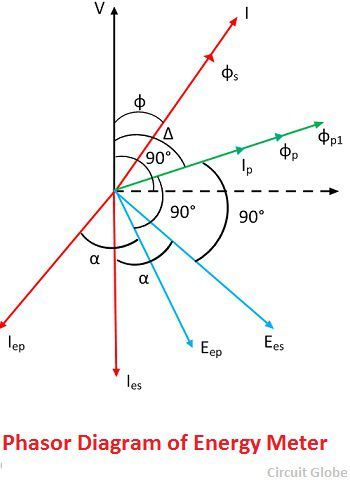
The phasor diagram of the energy meter is shown in the figure below.
Let
V – applied voltage
I – load current
∅ – the phase angle of load current
Ip – pressure angle of load
Δ – the phase angle between supply voltage and pressure coil flux
f – frequency
Z – impedance of eddy current
∝ – the phase angle of eddy current paths
Eep – eddy current induced by flux
Iep – eddy current due to flux
Eev – eddy current due to flux
Ies – eddy current due to flux
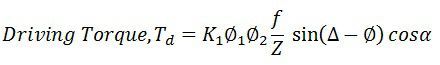
The net driving torque of the dis is expressed as
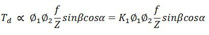
where K1 – constant
Φ1 and Φ2 are the phase angle between the fluxes. For energy meter, we take Φp and Φs.
β – phase angle between fluxes Φp and Φp = (Δ – Φ), therefore
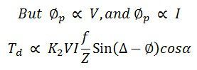
If f, Z and α are constants,
![]()
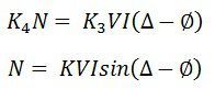
If N is steady speed, braking torque
![]()
At steady state, the speed of the driving torque is equal to the braking torque.
 If Δ = 90º,
Speed, 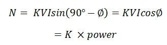
The speed of the rotation is directly proportional to the power.
![]()
If Δ = 90º, total number of revolutions
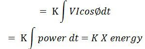
The three phase energy meter is used for measuring the large power consumption.
This article is really good ..
Nice Work.
Keep Posting.
Mention types of Electrical Energy Meter; also electronic energy meter(digital).
Thank You
good one and usefull one just keep it up
Maam keep it on . It is very important website for students.
What will happen if the neutral not going threw the kwh meter
Great to see the topic covered for energy meters
Good, easily understandable
Very good explanation
Clear and Simple. Well explained. Keep up your good work.
Super explanation
Good explanation
Best article , thank you 😘😘
Good Explanation.
Thank you.