Definition: The system which uses the direct current for the transmission of the power such type of system is called HVDC (High Voltage Direct Current) system. The HVDC system is less expensive and has minimum losses. It transmits the power between the unsynchronized AC system.
Component of an HVDC Transmission System
The HVDC system has the following main components.
- Converter Station
- Converter Unit
- Converter Valves
- Converter Transformers
- Filters
- AC filter
- DC filter
- High-frequency filter
- Reactive Power Source
- Smoothing Reactor
- HVDC System Pole
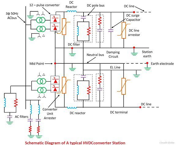
Converter Station
The terminal substations which convert an AC to DC are called rectifier terminal while the terminal substations which convert DC to AC are called inverter terminal. Every terminal is designed to work in both the rectifier and inverter mode. Therefore, each terminal is called converter terminal, or rectifier terminal. A two-terminal HVDC system has only two terminals and one HVDC line.
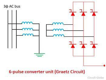
Converter Unit
The conversion from AC to DC and vice versa is done in HVDC converter stations by using three-phase bridge converters. This bridge circuit is also called Graetz circuit. In HVDC transmission a 12-pulse bridge converter is used. The converter obtains by connecting two or 6-pulse bridge in series.
Converter Valves
The modern HVDC converters use 12-pulse converter units. The total number of a valve in each unit is 12. The valve is made up of series connected thyristor modules.The number of thyristor valve depends on the required voltage across the valve. The valves are installed in valve halls, and they are cooled by air, oil, water or freon.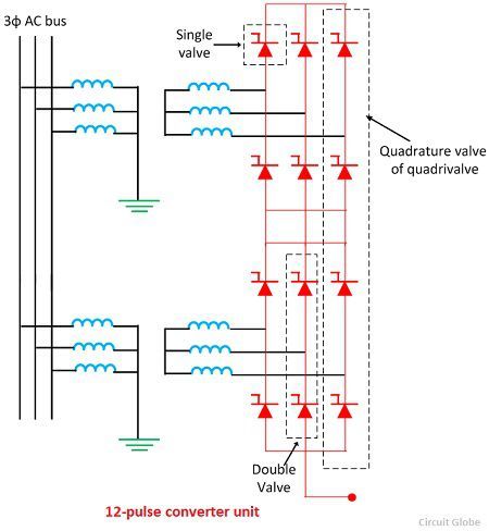
Converter Transformer
The converter transformer converts the AC networks to DC networks or vice versa. They have two sets of three phase windings. The AC side winding is connected to the AC bus bar, and the valve side winding is connected to valve bridge.These windings are connected in star for one transformer and delta to another.
The AC side windings of the two, three phase transformer are connected in stars with their neutrals grounded. The valve side transformer winding is designed to withstand alternating voltage stress and direct voltage stress from valve bridge. There are increases in eddy current losses due to the harmonics current. The magnetisation in the core of the converter transformer is because of the following reasons.
- The alternating voltage from AC network containing fundamentals and several harmonics.
- The direct voltage from valve side terminal also has some harmonics.
Filters
The AC and DC harmonics are generated in HVDC converters. The AC harmonics are injected into the AC system, and the DC harmonics are injected into DC lines. The harmonics have the following advantages.
- It causes the interference in telephone lines.
- Due to the harmonics, the power losses in machines and capacitors are connected in the system.
- The harmonics produced resonance in an AC circuit resulting in over voltages.
- Instability of converter controls.
The harmonics are minimised by using the AC, DC and high-frequency filters. The types of filter are explained below in details.
- AC Filters – The AC filters are RLC circuit connected between phase and earth. They offered low impedances to the harmonic frequencies. Thus, the AC harmonic currents are passed to earth. Both tuned and damped filters are used. The AC harmonic filter also provided a reactive power required for satisfactory operation of converters.
- DC Filters – The DC filter is connected between the pole bus and neutral bus. It diverts the DC harmonics to earth and prevents them from entering DC lines. Such a filter does not require reactive power as DC line does not require DC power.
- High-Frequency Filters – The HVDC converter may produce electrical noise in the carrier frequency band from 20 kHz to 490 kHz. They also generate radio interference noise in the megahertz range frequencies. High-frequency filters are used to minimise noise and interference with power line carrier communication. Such filters are placed between the converter transformer and the station AC bus.
Reactive Power Source
Reactive power is required for the operations of the converters. The AC harmonic filters provide reactive power partly. The additional supply may also be obtained from shunt capacitors synchronous phase modifiers and static var systems. The choice depends on the speed of control desired.
Smoothing Reactor
Smoothing reactor is an oil filled oil cooled reactor having a large inductance. It is connected in series with the converter before the DC filter. It can be located either on the line side or on the neutral side. Smoothing reactors serve the following purposes.
- They smooth the ripples in the direct current.
- They decrease the harmonic voltage and current in the DC lines.
- They limit the fault current in the DC line.
- Consequent commutation failures in inverters are prevented by smoothing reactors by reducing the rate of rising of the DC line in the bridge when the direct voltage of another series connected voltage collapses.
- Smoothing reactors reduce the steepness of voltage and current surges from the DC line. Thus, the stresses on the converter valves and valve surge diverters are reduced.
HVDC System Pole
The HVDC system pole is the part of an HVDC system consisting of all the equipment in the HVDC substation. It also interconnects the transmission lines which during normal operating condition exhibit a common direct polarity with respect to earth. Thus the word pole refers to the path of DC which has the same polarity with respect to earth. The total pole includes substation pole and transmission line pole.
Types of an HVDC System
The different types of an HVDC system are explained below in details.
Back-to-Back HVDC Station
The HVDC system which transfers energy between the AC buses at the same location is called back-to-back system or an HVDC coupling system. In back-to-back HVDC stations, the converters and rectifiers are installed in the same stations. It has no DC transmission line.
The back-to-back system provides an asynchronous interconnection between the two adjacent independently controlled AC networks without transferring frequency disturbances. The back-to-back DC link reduces the overall conversion cost, improve the reliability of the DC system. Such type of system is designed for bipolar operation.
Two Terminal HVDC System
The terminal with two terminals (converter station) and one HVDC transmission line is called two terminal DC system point-to-point system. This system does not have any parallel HVDC line and no intermediate tappings. The HVDC circuit breaker is also not required for two-terminal HVDC system.The normal and abnormal current is controlled effective converter controller.
Multiterminal DC (MTDC) System
This system has more than two converter station and DC terminal lines. Some of the converter stations operate as rectifier while others operate as an inverter. The total power taken from the rectifier station is equal to the power supplied by the inverter station. There are two type of MTDC Systems
- Series MTDC System
- Parallel MTDC System
In series MTDC system the converters are connected in series while in parallel MTDC system, the converters are connected in parallel. The parallel MTDC system may be operated without the use of an HVDC circuit breaker.
Advantages of MTDC systems
The following are the advantages of MTDC systems
- The MTDC system is more economical and flexible.
- The frequency oscillation in the interconnected AC networks can be damped quickly.
- The heavily load AC networks can be reinforced by using MTDC systems.
Applications of MTDC systems
The following are the applications of the HVDC systems
- It transfers the bulk power from several remote generating sources to several load centres.
- The systems are interconnected between two or more AC systems by radial MTDC systems.
- It reinforces the heavy load urban AC networks by MTDC systems
HVDC circuit breaker is used in two terminal DC link and Multiterminal DC link for transferring from ground to metallic run.
Thanks.
Thank you very much. Can you explain what is the use of DC pole bus.
THANK YOU FROM ARGENTINA
Very well explained! 👍
Thankyou from Pakistan!
Thank you,the explanation is very well detailed.
Thank you!
Thank you