Consider a synchronous machine connected to an infinite bus through a transmission line of reactance Xl shown in a figure below. Let us assume that the resistance and capacitance are neglected.
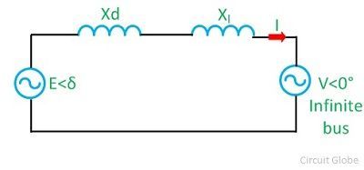 Equivalent diagram of synchronous machine connected to an infinite bus through a transmission line of series reactance Xl is shown below:
 Let,
Let,
V = V<0⁰ – voltage of infinite bus
E = E<δ – voltage behind the direct axis synchronous reactance of the machine.
Xd = synchronous / transient resistance of the machine
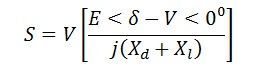
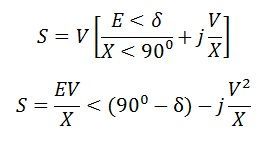
The complex power delivered by the generator to the system is
S = VI
 Let,
Let, ![]()
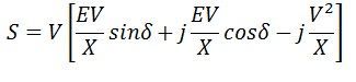
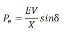
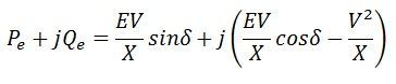 Active power transferred to the system
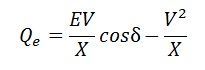
 The reactive power transferred to the system
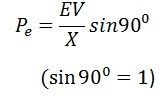
 The maximum steady-state power transfers occur when δ = 0

![]() The graphical representation of Pe and the load angle δ is called the power angle curve. It is widely used in power system stability studies. The power angle curve is shown below
The graphical representation of Pe and the load angle δ is called the power angle curve. It is widely used in power system stability studies. The power angle curve is shown below
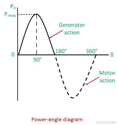 Maximum power is transferred when δ = 90⁰. As the value of load angle δ is above 90, Pe decrease and becomes zero at δ = 180⁰. Above 180⁰, Pe becomes negative, which show that the direction of power flow is reversed, and the power is supplied from infinite bus to the generator. The value of Pe is often called pull out power. It is also called the steady-state limit.
The total reactance between two voltage sources E and X is called the transfer reactance. The maximum power limit is inversely proportion to the transfer reactance.
Thanks for the topic.