In Half Wave Rectifier, when the AC supply is applied at the input, a positive half cycle appears across the load, whereas the negative half cycle is suppressed. This can be done by using the semiconductor PN junction diode. The diode allows the current to flow only in one direction. Thus, converts the AC voltage into DC voltage.
Circuit Diagram of Half Wave Rectifier
In half-wave rectification, only one crystal diode is used. It is connected in the circuit as shown below.
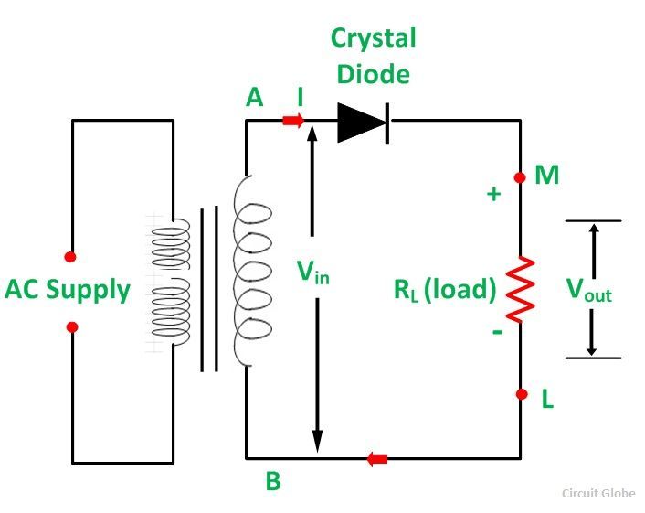
The AC supply to be rectified is generally given through a transformer. The transformer is used to step down or step up the main supply voltage as per the requirement. It also isolates the rectifier from power lines and thus reduces the risk of electric shock.
Operation of Half Wave Rectifier
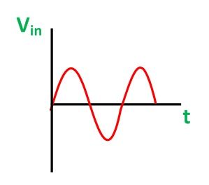
When AC supply is switched ON the alternating voltage (Vin) shown in the figure below appears across the terminal AB at the secondary winding.
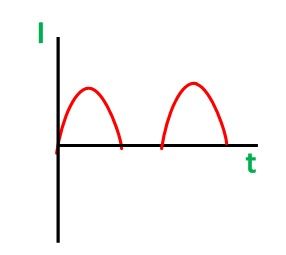
During the positive half cycle, terminal A is positive with respect to B and the crystal diode is forward biased. Therefore, it conducts and current flows through the load resistor RL. This current varies in magnitude as shown in the wave diagram shown below.
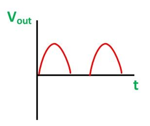
Thus, a positive half cycle of the output voltage (Vout = iRL) appears across the load resistor RL shown in the figure below.
Peak Inverse Voltage
During the negative half-cycle when the diode is reverse biased the maximum value of the voltage coming across the diode is called the peak inverse voltage. As the current flows through the load resistor RL, only in one direction, i.e., from M to L. Hence, a DC output is obtained across RL, which is pulsating in nature.
Disadvantages of the Half Wave Rectifier
The disadvantages of the half-wave rectifier are as follows:
- The output is low because the AC supply delivers power only half of the time.
- The output contains more alternating component (ripples). Therefore, it needs a heavy filter circuit to smooth out the output.
Full Wave Rectifier
In Full Wave Rectification, when the AC supply is applied at the input, during both the half-cycles (i.e., positive as well as negative) current flows through the load in the same direction. This can be achieved by using two crystal diodes. The two diodes conduct the current alternately.
To obtain the same direction of flow of current in the load resistors RL during positive as well as the negative half cycle of input, the two circuits are used. They are named as follows:-
To have detailed explanation on the two types of full wave rectifiers follow the links given above.
Nice and simple explanation ,Thanks
Welcome
Good
Nice
Easy to understand ,thank u
Thanks
Good Example