Definition: The self-controlled variable frequency drive employing a sinusoidal PMAC (Permanent Magnet Alternating Current) motor is called brushless DC motor drive. The brushless DC motor drive has some advantages like practically they require no maintenance and have a long life. They also have low frequency, low inertia and friction, and low radio frequency interference and noise. The only disadvantage of the drive is that they have high costs and low starting torque.
The brushless DC motor drive is used in record players, the tape drive for recorders, spindle drive in hard disks for computers, and low power drives in computers peripherals instruments and control systems. They also have applications in aerospace, in biomedical and in driving cooling fans, etc.
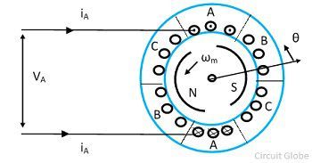
The cross section of a three-phase two pole trapezoidal PMAC motor is shown in the figure below. This drive has a permanent magnet rotor with wide pole arc. The stator of the drive has three poles winding which is displaced by 120º and each phase winding spans 60º on each side.
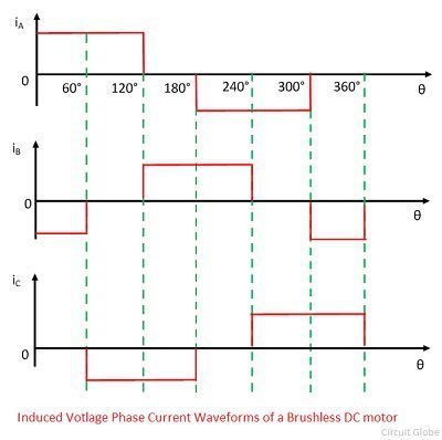
The voltage induces in three phases are shown in the figure below. The reason for getting the trapezoidal waveform is that when the rotor revolving in a counter-clockwise direction, then up to 120º rotation from the position all the top conductor of phase A will linking the south pole and all the bottom of phase A will be linking the north pole.
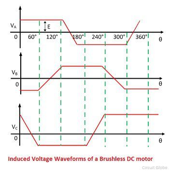
The voltage induces in phase A will be the same during 120º rotations and beyond the 120º some conductors in the top link north pole and others the south pole. Similarly, the voltage induces in the bottom conductors. The wave voltage induces in phase A linearly reverse in next 60º rotation. Similarly, the voltage induces in the phases B and C.
The brushless DC motor drive uses voltage source inverter and trapezoidal PMAC motor shown in the figure below. The stator windings are star connected. The phase voltage waveform for a trapezoidal PMAC motor is shown in the figure below.
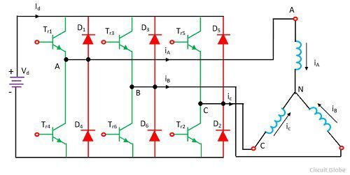
The stator winding is fed with a current pulse, and each of the pulses had duration 120º and located in the region where induced voltage is constant and maximum. The polarity of the current pulse is same as that of the induced voltage. The air gap flux is constant and the voltage induced is proportional to the speed of the rotor.
![]()
During each 60º internal the current enters one phase and come out of another phase, therefore power supplied to the motor in each such interval is expressed as
![]()
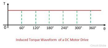
The torque developed by the motor
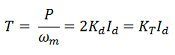
The waveform of the torque is given by the figure shown below. The torque is proportional to the current flows in the DC power links. The regenerative breaking of the drive is obtained by reversing the phase current and hence the current source Id will also reverse. The power flows from the machine to inverter and from the inverter to DC source.
When the drive speed reversed the polarity of induces voltages reversed and the drive gives regenerative braking operation, and when the current direction is reversed the motoring operation is obtained. The current waveforms are shown in the figure below.
Types of Brushless DC Motor Drive
The brushless DC motor drive is mainly classified into two types, i.e., the low-cost brushless dc motor drive and the single-phase brushless dc motor drive.Their types are explained below in details.
Low-Cost Brushless DC Motor Drive
This drive has only three transistors and three diode converter which can supply only positive current or voltage to three phase motor. The induced voltage and current supplied to the motor for motoring and braking operation. When 120º positive current pulses are supplied to the motor, then the motoring action is obtained in a counter-clockwise direction. When these pulses are shifted to 180º, then the braking action is obtained
 The current of phase A is controlled by the thyristor Tr1 and the diode D1. When Tr1 is on source Vd is connected across winding A and rate of change of IA is positive. When Tr1 is turned off current iA freewheels through diode D1 and rate of change of iA is negative. Thus, during the period from 0 to 120º, Tr1 can be alternately turn on and off. So that current IA is made to follow a rectangular reference current iA within a hysteresis band.
Single-Phase Brushless DC Motor Drive
The single-phase brushless DC motor drive is shown in the figure below. Let us consider the motor is supplied from the half bridge single phase converter with a rectangular current waveform as shown in the figure.
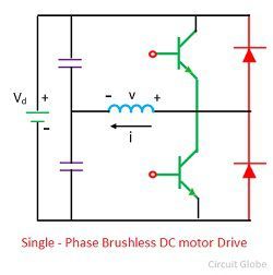
The torque produced by the motor has a large ripple. When the motor is running at large speed, the torque rippled will be filtered out by the inertia of the motor load system which is giving a uniform speed.