The Equivalent Circuit of an Induction motor enables the performance characteristics which are evaluated for steady-state conditions. An induction motor is based on the principle of induction of voltages and currents. The voltage and current are induced in the rotor circuit from the stator circuit for the operation. The equivalent circuit of an induction motor is similar to that of the transformer.
Contents:
Stator Circuit Model
The stator circuit model of an induction motor consists of a stator phase winding resistance R1, stator phase winding leakage reactance X1 as shown in the circuit diagram below:
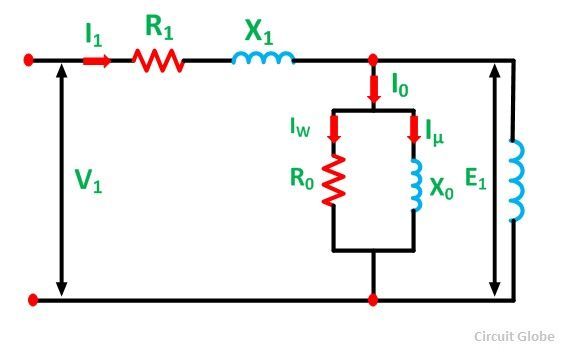 The no-load current I0 is simulated by a pure inductive reactor X0 taking the magnetizing component Iµ and a non-inductive resistor R0 carrying the core loss current Iω. Thus,
![]()
The total magnetizing current I0 is considerably larger in the case of the induction motor as compared to that of a transformer. This is because of the higher reluctance caused by the air gap of the induction motor. As we know that, in a transformer, the no-load current varies from 2 to 5% of the rated current, whereas in an induction motor the no-load current is about 25 to 40% of the rated current depending upon the size of the motor. The value of the magnetizing reactance X0 is also very small in an induction motor.
Rotor Circuit Model
When a three phase supply is applied to the stator windings, a voltage is induced in the rotor windings of the machine. The greater will be the relative motion of the rotor and the stator magnetic fields, the greater will be the resulting rotor voltage. The largest relative motion occurs at the standstill condition. This condition is also known as the locked rotor or blocked rotor condition. If the induced rotor voltage at this condition is E20 then the induced voltage at any slip is given by the equation shown below:![]()
The rotor resistance is constant and is independent of the slip. The reactance of the induction motor depends upon the inductance of the rotor and the frequency of the voltage and current in the rotor.
If L2 is the inductance of the rotor, the rotor reactance is given by the equation shown below:![]()
But, as we know,![]()
Therefore,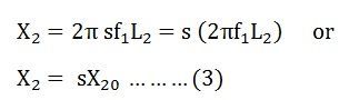
Where X20 is the standstill reactance of the rotor.
The rotor circuit is shown below:
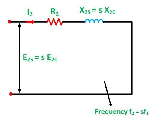
The rotor impedance is given by the equation below: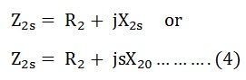
The rotor current per phase is given by the equation shown below: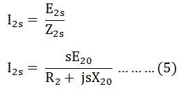
Here, I2 is the slip frequency current produced by a slip frequency induced voltage sE20 acting in the rotor circuit having an impedance per phase of (R2 + jsX20).
Now, dividing the equation (5) by slip s we get the following equation: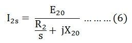
The R2 is a constant resistance and a variable leakage reactance sX20. Similarly, the rotor circuit shown below has a constant leakage reactance X20 and a variable resistance R2/s.
Equation (6) above explains the secondary circuit of an imaginary transformer, with a constant voltage ratio and with the same frequency of both sides. This imaginary stationary rotor carries the same current as of the actual rotating rotor. This makes it possible to transfer the secondary rotor impedance to the primary stator side.
Approximate Equivalent Circuit of an Induction Motor
The equivalent circuit is further simplified by shifting the shunt impedance branches R0 and X0 to the input terminals as shown in the circuit diagram below:
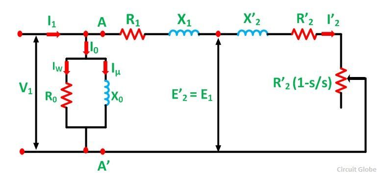 The approximate circuit is based on the assumption that V1 = E1 = E’2. In the above circuit, the only component that depends on the slip is the resistance. All the other quantities are constant. The following equations can be written at any given slip s is as follows:
Impedance beyond AA’ is given as: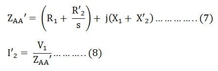
Putting the value of ZAA’ from the equation (7) in equation (8) we get,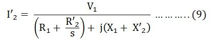
Therefore,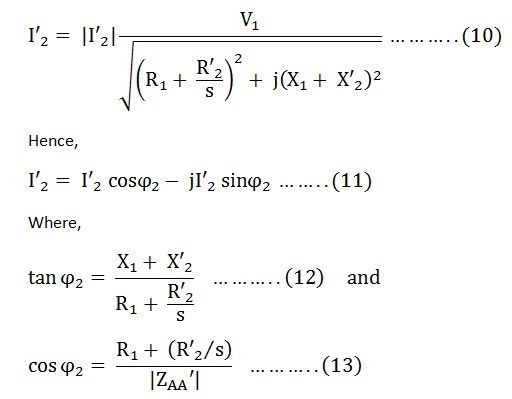
No-load current I0 is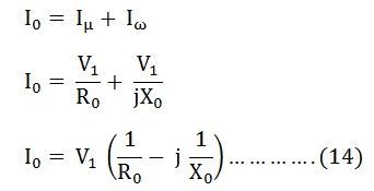
The total stator current is given by the equation shown below: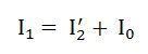
Total core losses are given by the equation shown below: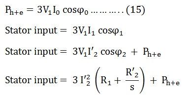
The air gap power per phase is given as: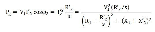 The developed torque is given by the equation shown below:
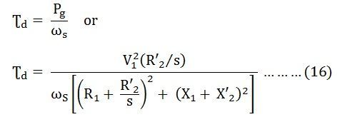
The above equation is the torque equation of an induction motor. The approximate equivalent circuit model is the standard for all performance calculations of an induction motor.