The equivalent circuit of a Single Phase Induction Motor can be obtained by two methods named the Double Revolving Field Theory and Cross Field Theory. Firstly the equivalent circuit is developed on the basis of double revolving field theory when only its main winding is energized.
Considering the case when the rotor is stationary and only the main winding is excited. The motor behaves as a single-phase transformer with its secondary short circuit. The equivalent circuit diagram of the single phase motor with only its main winding energized is shown below:
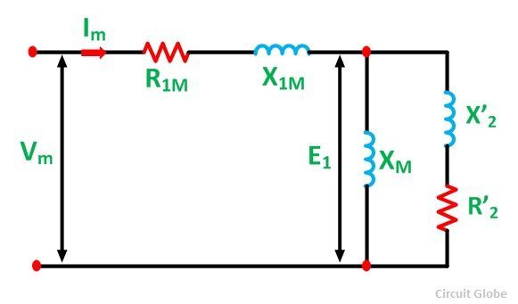
Here,
- R1m is the resistance of the main stator winding.
- X1m is the leakage reactance of the main stator winding.
- XM is the magnetizing reactance.
- R’2 is the standstill rotor resistance referred to as the main stator winding.
- X’2 is the standstill rotor leakage reactance referred to as the main stator winding.
- Vm is the applied voltage.
- Im is the main winding current.
The core loss will be assumed to be lumped with the mechanical and stray losses as a part of the rotational losses of the rotor. The pulsating air gap flux in the motor at the standstill is resolved into two equal and opposite fluxes with the motor. The standstill impedance of each of the rotors referred to as the main stator winding is given as: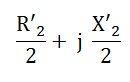
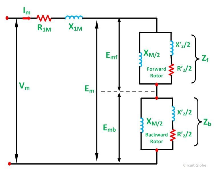
The equivalent circuit of a single-phase single winding induction motor with the standstill rotor is shown below. The forward and the backward flux induces a voltage Emf and Emb respectively in the main stator winding. Em is the resultant induced voltage in the main winding.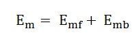
At the standstill condition Emf = Emb
Now, with the help of an auxiliary winding, the motor is started. As the motor attains its normal speed, the auxiliary winding is removed. The effective rotor resistance of an induction motor depends on the slip of the rotor.
In the above circuit diagram, the air gap portion is split into two parts. The first part shows the effect of forward rotating flux and the second part shows the effect of the backward rotating flux. The effective rotor resistance with respect to the forward rotating flux is R’2/2S and with respect to the backward rotating flux is R’2/2 (2-s).
When both forward and backward slips are taken into account, the equivalent circuit shown below is formed. In this condition, the motor is running on the main winding alone.
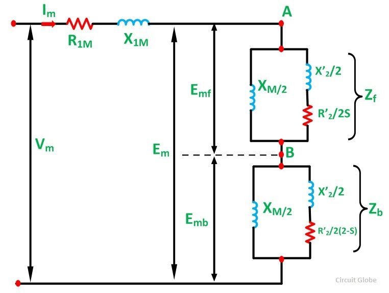
The rotor impedance representing the effect of the forward field referred to the stator winding m is given by an impedance shown below: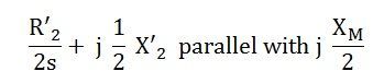
The rotor impedance of a single phase induction motor representing the effect of the backward field referred to the stator winding m is given by an impedance shown below: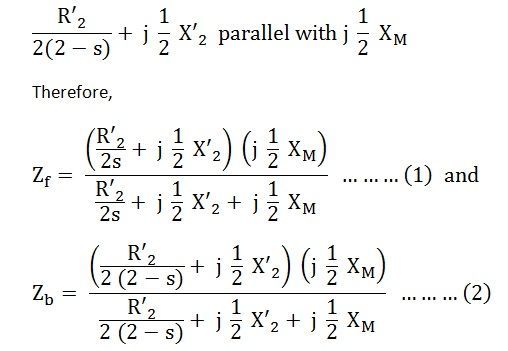
The simplified equivalent circuit of a single-phase induction motor with only its main winding energized is shown in the figure below: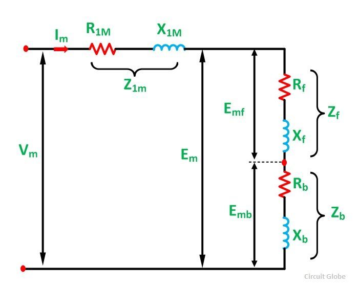
Here,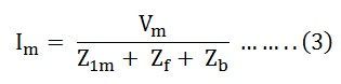
The above equation (3) is the equation of the current in the stator winding.
How we can prove with the help of double field revolving theory that for a single phase induction motor, under running condition Emf>> Emb, where the symbols have their usual meanings??