The equivalent circuit diagram of any device can be quite helpful in the pre-determination of the behavior of the device under the various condition of operation. It is simply the circuit representation of the equation describing the performance of the device.
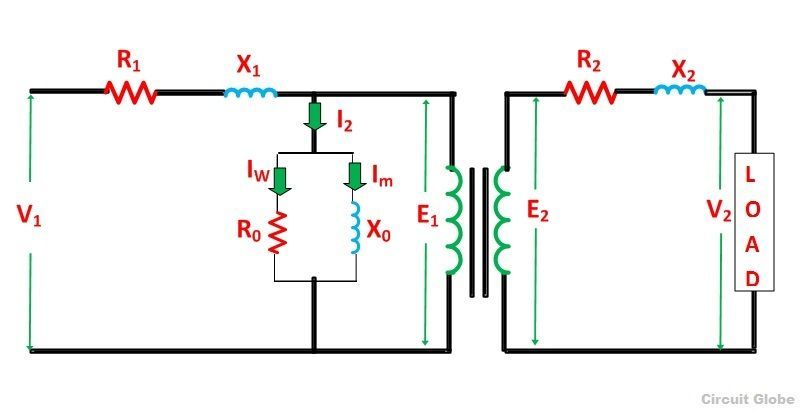
The simplified equivalent circuit of a transformer is drawn by representing all the parameters of the transformer either on the secondary side or on the primary side. The equivalent circuit diagram of the transformer is shown below:
Contents:
- Equivalent Circuit When all the Quantities are Referred to Primary side
- Equivalent Circuit When all the Quantities are Referred to Secondary side
Let the equivalent circuit of a transformer having the transformation ratio K = E2/E1
The induced emf E1 is equal to the primary applied voltage V1 less primary voltage drop. This voltage causes current I0 no-load current in the primary winding of the transformer. The value of no-load current is very small, and thus, it is neglected.
Hence, I1 = I1’. The no-load current is further divided into two components called magnetizing current (Im) and working current (Iw).
These two components of no-load current are due to the current drawn by a non-inductive resistance R0 and pure reactance X0 having voltage E1 or (V1 – primary voltage drop).
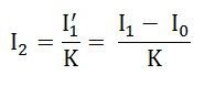
The secondary current I2 is
The terminal voltage V2 across the load is equal to the induced emf E2 in the secondary winding less voltage drop in the secondary winding.
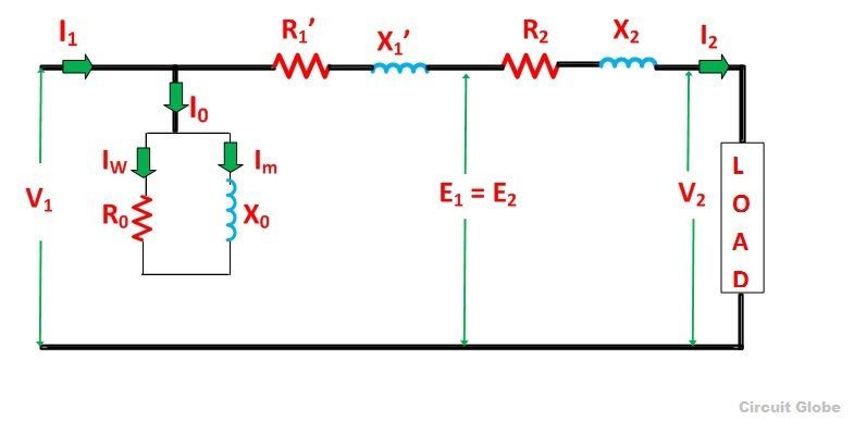
Equivalent Circuit when all the quantities are referred to Primary side
In this case, to draw the equivalent circuit of the transformer all the quantities are to be referred to the primary as shown in the figure below:
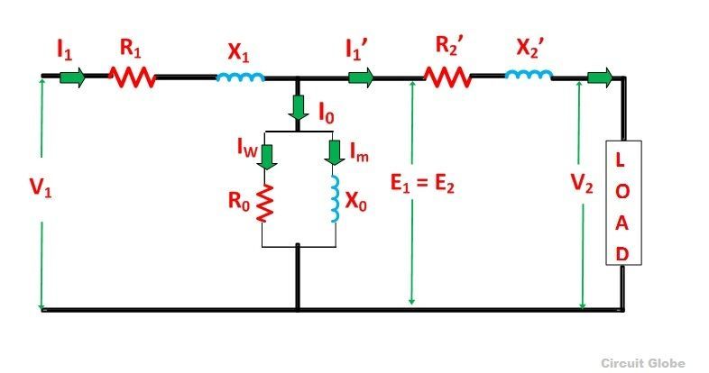
The following are the values of resistance and reactance given below
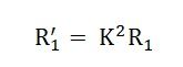
Secondary resistance referred to the primary side is given as:
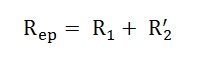
The equivalent resistance referred to the primary side is given as:
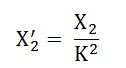
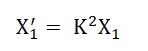
Secondary reactance referred to the primary side is given as:
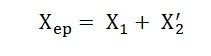
The equivalent reactance referred to the primary side is given as:
Equivalent Circuit when all the quantities are referred to Secondary side
The equivalent circuit diagram of the transformer is shown below when all the quantities are referred to the secondary side.
The following are the values of resistance and reactance given below
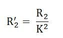
Primary resistance referred to the secondary side is given as
The equivalent resistance referred to the secondary side is given as
![]()
Primary reactance referred to the secondary side is given as
The equivalent reactance referred to the secondary side is given as
![]()
No-load current I0 is hardly 3 to 5% of full load rated current, the parallel branch consisting of resistance R0 and reactance X0 can be omitted without introducing any appreciable error in the behavior of the transformer under the loaded condition.
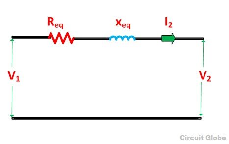
Further simplification of the equivalent circuit of the transformer can be done by neglecting the parallel branch consisting of R0 and X0.
The simplified circuit diagram of the transformer is shown below:
This is all about the equivalent circuit of the Transformer.
helpful article
Good one. Thanku
easily understandable.
My professor didn’t even explain this. Thanks