The open circuit and short circuit test are performed for determining the parameter of the transformer like their efficiency, voltage regulation, circuit constant etc. These tests are performed without the actual loading and because of this reason the very less power is required for the test. The open circuit and the short circuit test gives a very accurate result as compared to the full load test.
Contents:
- Open Circuit Test
- Calculation of Open Circuit Test
- Short Circuit Test
- Calculation of Short Circuit Test
Open Circuit Test
The purpose of the open-circuit test is to determine the no-load current and losses of the transformer because of which their no-load parameters are determined. This test is performed on the primary winding of the transformer. The wattmeter, ammeter and the voltage are connected to their primary winding. The nominal rated voltage is supplied to their primary winding with the help of the ac source.
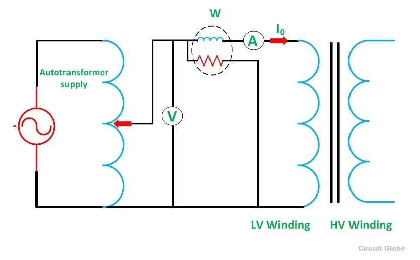
The secondary winding of the transformer is kept open, and the voltmeter is connected to their terminal. This voltmeter measures the secondary induced voltage. As the secondary of the transformer is open, thus no-load current flows through the primary winding.
The value of no-load current is very small as compared to the full rated current. The copper loss occurs only on the primary winding of the transformer because the secondary winding is open. The reading of the wattmeter only represents the core and iron losses. The core loss of the transformer is the same for all types of loads.
Calculation of open-circuit test
Let,
- W0 – wattmeter reading
- V1 – voltmeter reading
- I0 – ammeter reading
Then the iron loss of the transformer Pi = W0 and
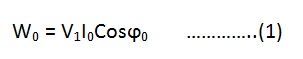
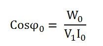
The no-load power factor is
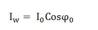
Working component Iw is
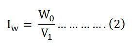
Putting the value of W0 from the equation (1) in equation (2) you will get the value of the working component as
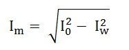
Magnetizing component is
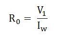
No-load parameters are given below:
Equivalent exciting resistance is
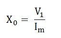
Equivalent exciting reactance is
The phasor diagram of the transformer at no load or when an open circuit test is performed is shown below
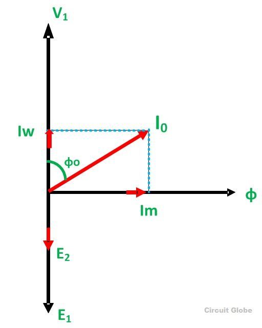
The iron losses measured by the open circuit test is used for calculating the efficiency of the transformer.
Short Circuit Test
The short circuit test is performed for determining the below mention parameter of the transformer.
- It determines the copper loss occur on the full load. The copper loss is used for finding the efficiency of the transformer.
- The equivalent resistance, impedance, and leakage reactance are known by the short circuit test.
The short circuit test is performed on the secondary or high voltage winding of the transformer. The measuring instrument like wattmeter, voltmeter and ammeter are connected to the high voltage winding of the transformer. Their primary winding is short-circuited by the help of thick strip or ammeter which is connected to its terminal.
The low voltage source is connected across the secondary winding because of which the full load current flows from both the secondary and the primary winding of the transformer. The full load current is measured by the ammeter connected across their secondary winding.
The circuit diagram of the short circuit test is shown below:

The low voltage source is applied across the secondary winding, which is approximately 5 to 10% of the normal rated voltage. The flux is set up in the core of the transformer. The magnitude of the flux is small as compared to the normal flux.
The iron loss of the transformer depends on the flux. It is less occur in the short circuit test because of the low value of flux. The reading of the wattmeter only determines the copper loss occurred, in their windings. The voltmeter measures the voltage applied to their high voltage winding. The secondary current induces in the transformer because of the applied voltage.
Calculation of Short Circuit Test
Let,
- Wc – Wattmeter reading
- V2sc – voltmeter reading
- I2sc – ammeter reading
Then the full load copper loss of the transformer is given by
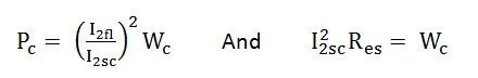
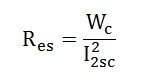
Equivalent resistance referred to the secondary side is
The phasor diagram of the short circuit test of the transformer is shown below
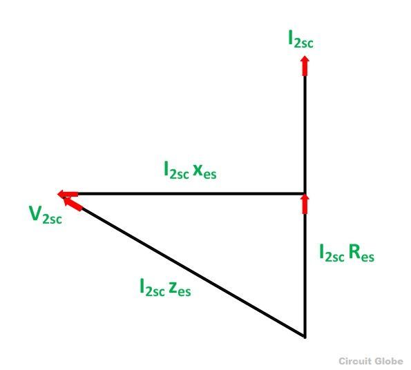
From the phasor diagram
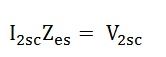
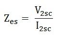
Equivalent impedance referred to the secondary side is given by
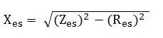
The equivalent reactance referred to the secondary side is given by
The voltage regulation of the transformer can be determined at any load and power factor after knowing the values of Zes and Res.
In the short circuit test the wattmeter record, the total losses, including core loss but the value of core loss are very small as compared to copper loss so the core loss can be neglected.
Thanks for explaining the process of open circuit and short circuit test. Can you add some mathematical example here? I need to do some math about open circuit and short circuit test. So I’m finding an online calculator
Do you think this calculator will provide me correct answer?
Yes, this calculator gives the accurate result.
Thanks.
Thank you so much mam……for this
How can i differenciate primary winding losses from seccondary’s?
the matter is: with this calculations you’ll have the equivalent resistance for Primary winding, but i need the seccondary resistance. can you give me a way to find it?
Thank you in advance.
F.N.
Amazing
Thanks for your valuable formulas
Thanks for this explanation it is helping a lot
Thanks for well-explained details related to short cct and open cct tests on transformer.
It was very helpful
Thank you
Thanks
Thanks a lot✌