One of the crucial difference between diode and thyristor is that a diode is a two terminal device used for rectification and switching applications. As against a thyristor is a three terminal device used for switching purpose. This generates the major difference in their operation.
We know both diode and thyristor are semiconductor devices formed by the combination of p and n type semiconductor material. However, various factors exist that differentiates the two.
Content: Diode Vs Thyristor
Comparison Chart
| Basis for Comparison | Diode | Thyristor (SCR) |
|---|---|---|
| Symbol | 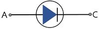 | 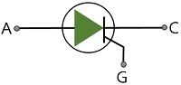 |
| Device Type | Uncontrolled rectifying device (as triggering pulse is not required). | Controlled turn-on device (as triggering pulse is needed). |
| Number of layers | 2 | 4 |
| Number of junctions | 1 | 3 |
| Number of terminals | 2 (Anode and Cathode) | 3 (Anode, Cathode and Gate) |
| Power handling ability | Good | Better |
| Operating Voltage | Low | Comparatively high |
| Cost | Less expensive | More expensive |
| Weight | Light weighted | Comparatively heavy |
Definition of Diode
A diode is a two terminal device formed by the combination of a p and an n type semiconductor material that allows conduction in single direction only. Practically it is said that the diode allows conduction only when forward biased and restricts the flow of current in reverse biased condition.
The figure given below represents a forward biased p-n junction diode:
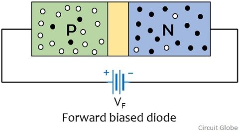
Initially when no external potential is provided then also the majority carriers of both the regions drift across the junction in order to combine. After a certain point of time, immobile ions get deposited on both sides of the junction, thereby producing a depletion region.
Once the depletion layer gets generated then further movement of charge carriers will take place only when external biasing will be provided. So, when forward biasing is provided then holes and electrons from p and n side respectively gets repelled by the positive and negative terminal of the battery. This reduces the width of the depletion region and carriers drift across the junction by the action of external potential.
This movement of carriers generate electric current through the device and the direction of flow of current will be opposite to the direction of flow of electrons.
The figure given below represents the reverse biased condition of the p-n junction diode:
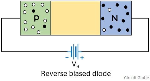
Here we can clearly see that the p region is connected to the negative and n region is connected to the positive terminal of the battery.
So, now the majority charge carriers of both the regions experiences attractive force from the battery terminal. This leads to broadening of the depletion region and hence the barrier potential increases. And so, this will cause no further flow of current through the device.
Definition of Thyristor
Thyristor is a 4 layer device formed by alternate combination of p and n type semiconductor materials. It is a device used for rectification and switching purpose. SCR is the mostly used member of thyristor family and it is the name commonly used when we talk about thyristors. SCR also allows the flow of current in one direction and its action is controlled by an external trigger pulse applied at its gate terminal.
Basically SCR is a 4-layer device in the configuration P-N-P-N. This configuration generates 3 junctions in the structure of SCR. Let us now understand in brief how an SCR basically operates:
As we have already discussed that the operation of a thyristor majorly depends on the applied external potential at the gate terminal. So, let us understand the case when no any external potential is provided at the gate terminal but forward voltage is applied between anode and cathode.
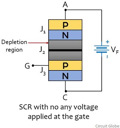
Hence, as we can see in the figure shown above that forward voltage is applied between anode and cathode that causes the junction J1 and J3 to be forward biased. But as the same time junction J2 will be reverse biased. This will lead to generation of depletion region around J2. Hence no forward current will flow through the device and only negligibly small leakage current will flow through it. This state is said to be practically off state of the thyristor(SCR).
Now, suppose if no any external gate potential is applied but a reverse potential is applied between anode and cathode. This biasing arrangement reverse biases the junction J1 and J3 but forward biases the junction J2. Still only the leakage current will flow through the device.
Hence we can say without any gate potential, SCR will not conduct in either forward or reverse biased condition. Let us now consider the case when gate terminal is triggered with a forward potential. Also a forward voltage is provided between cathode and anode.
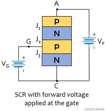
So in this case, the electrons present in the n region experiences repulsion from the negative terminal of the battery. This movement generates gate current through the device. Also the holes in the p region gets repelled by the positive terminal of the battery and drift across the junction J2 thereby giving rise to anode current.
This regenerative action allows the SCR to conduct heavily. However, it is to be noteworthy here that once the SCR starts conducting, then the gate potential plays no any further role in conduction. And the device continues to be in ON state.
Key Differences Between Diode and Thyristor
- A diode is a two-layer device having a p and an n region. While a thyristor is a four-layer semiconductor device formed by alternate arrangement of p and n type material.
- Due to 2 layers in diode, there exist a single junction in case of diode. Whereas due to 4 layers, the thyristor has 3 junctions.
- A diode is a 2 terminal device namely anode and cathode. But a thyristor is a 3 terminal device, out of the 3 terminal, 2 are anode and cathode while the other is gate which is used to provide external triggering to the circuit.
- The power handling ability of thyristors is comparatively better than the diodes.
- Diodes exhibits low operating voltage nearly about 5000 V. While, the operating voltage is around 7000 V in case of thyristors which is comparatively higher than diodes.
- Diode is such a device which does not requires external triggering pulse in order to initiate conduction. While thyristor needs external triggering pulse for the circuit operation.
- Diodes are less costly when compared with thyristors.
- Thyristors are comparatively bulky than diodes.
Conclusion
So, from the above discussion we can say that though both diode and thyristor are semiconductor devices. But the operation of the two are quite different thus find applications in different fields.
Also diodes are widely used in rectification circuit, clippers and clampers, logic gates and in voltage multiplier circuits. While thyristors are widely used in high power motors, inverters, in controlled rectification circuits, timing and over voltage protection circuits.