Definition: The capacitive voltage transformer step-down the high voltage input signals and provide the low voltage signals which can easily measure through the measuring instrument. The Capacitive voltage transformer (CVT) is also called capacitive potential transformer
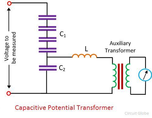
The capacitive potential divider, inductive element and the auxiliary transformer are the three main parts of the capacitive potential transformer.
 What is the need of CVT?
For measuring high voltage (above 100kV) the high insulated transformer is required. The highly insulated transformer is quite expensive as compared to the normal transformer. For reducing the cost, the capacitive potential transformer is used in the system. The CVT is cheap, and their performance is not much inferior to the highly insulated transformer.
Capacitive Voltage Transformer Working
The capacitive potential divider is used in combination with the auxiliary transformer and the inductive element. The capacitive potential divider step-down the extra high voltage signals into a low voltage signal. The output voltage of the capacitive potential transformer is further step-down by the help of the auxiliary transformer.
Consider the circuit diagram of the capacitive potential transformer.
 The capacitor or potential divider is placed across the line whose voltage is used to be measured or controlled. Let the C1 and C2 be the capacitor placed across the transmission lines. The output of the potential divider acts as an input to the auxiliary transformer.
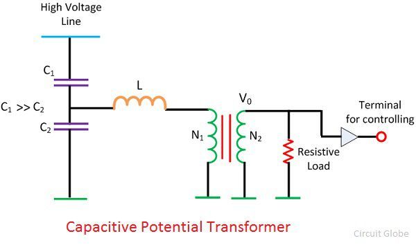
The capacitor places near to the ground have high capacitances as compared to that placed near the transmission line. The high value of capacitances means the impedance of that part of the potential divider becomes low. Thus, low voltages pass to the auxiliary transformer. The auxiliary transformer further step-down the voltages.
The N1 and the N2 are the numbers of turns on the primary and the secondary winding of the transformer. The meter used for measuring the low value of voltage is resistive, and the potential divider is capacitive. Thereby, the phase shift occurs, and the output will be affected. To overcome this problem, the inductance is placed in series with the auxiliary transformer.
This inductance L consists the leakage flux of the auxiliary winding of the auxiliary transformer. The value of inductances is given as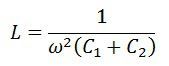 The value of inductances is adjustable. The inductance compensates the voltage drops occurs in the transformer because of the reduction of the current from the potential divider. But, in actual practice, the compensation is not possible because of the inductance losses.
The voltage turn ratio of the transformer is expressed as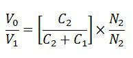 As the value of C1 is greater than the C2. Thus the value C1/(C1+C2) is small. The low value of voltage is obtained.
The voltage transformation ratio of the capacitive potential transformer is free from the burden. The burden is the load on the secondary winding of the transformer
well expalined!!!!!
I would like to study more from this site.