The Blocked Rotor Test of an induction motor is similar to the short circuit test of a transformer. In this test, the shaft of the motor is locked so that it cannot move and the rotor winding is short-circuited. In the slip ring motor, the rotor winding is short-circuited through the slip rings. In the case of the cage motors, the rotor bars are permanently short-circuited. It is also known as the Locked Rotor Test.
The circuit diagram of the blocked rotor test is shown below:
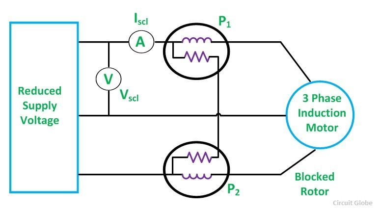
A reduced voltage at the reduced frequency is applied to the stator through a three-phase autotransformer so that full-load rated current flows in the stator. The following three readings are obtained from the blocked rotor test. They are as follows:
- Total power input on the short circuit Psc = algebraic sum of the two wattmeter readings
The power input on the locked rotor test is equal to the sum of copper losses of the stator and the rotor for all three phases. The core and the mechanical losses are negligible as the reduced voltage is applied to the stator and, as a result, the rotation of the rotor is not allowed.
- Reading of the ammeter
![]()
- Reading of the voltmeter
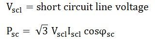
Where cosϕ is the power factor of the short circuit.
The equivalent resistance of the motor referred to the stator side is given by the equation shown below: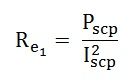
The equivalent impedance of the motor referred to the stator side is given by the equation shown below: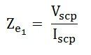 The equivalent reactance of the motor referred to the stator side is given by the equation shown below.
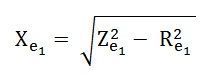
The blocked rotor test is performed under normal operating conditions when the rotor current and the frequency are on the same conditions. Generally, the slip of the induction motor varies between 2 to 4 percent, and the resulting rotor frequency is in the range of 1 to 2 hertz for the stator frequency of 50 hertz at the normal conditions.
This test should be performed at a reduced frequency. In order to obtain accurate results, the Blocked Rotor Test is performed at a frequency 25 percent or less than the rated frequency. The leakage reactances at the rated frequency are obtained by considering that the reactance is proportional to the frequency.
However, for the motor less than the 20-kilowatt rating, the effects of the frequency are negligible, and the blocked rotor test can be performed directly at the rated frequency.