Thevenin’s Theorem states that any complicated network across its load terminals can be substituted by a voltage source with one resistance in series. This theorem helps in the study of the variation of current in a particular branch when the resistance of the branch is varied while the remaining network remains the same.
For example in designing electrical and electronics circuits.
A more general statement of Thevenin’s Theorem is that any linear active network consisting of independent or dependent voltage and current source and the network elements can be replaced by an equivalent circuit having a voltage source in series with a resistance.
Where the voltage source being the open-circuited voltage across the open-circuited load terminals and the resistance being the internal resistance of the source.
In other words, the current flowing through a resistor connected across any two terminals of a network by an equivalent circuit having a voltage source Eth in series with a resistor Rth. Where Eth is the open-circuit voltage between the required two terminals called the Thevenin voltage and the Rth is the equivalent resistance of the network as seen from the two-terminal with all other sources replaced by their internal resistances called Thevenin resistance.
Contents:
Explanation of Thevenin’s Theorem
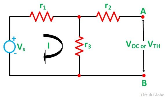
The Thevenin’s statement is explained with the help of a circuit shown below:
 Let us consider a simple DC circuit as shown in the figure above, where we have to find the load current IL by the Thevenin’s theorem.
In order to find the equivalent voltage source, rL is removed from the circuit as shown in the figure below and Voc or VTH is calculated.
So,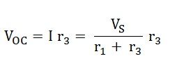
Now, to find the internal resistance of the network (Thevenin’s resistance or equivalent resistance) in series with the open-circuit voltage VOC , also known as Thevenin’s voltage VTH, the voltage source is removed or we can say it is deactivated by a short circuit (as the source does not have any internal resistance) as shown in the figure below:
Therefore,
So,
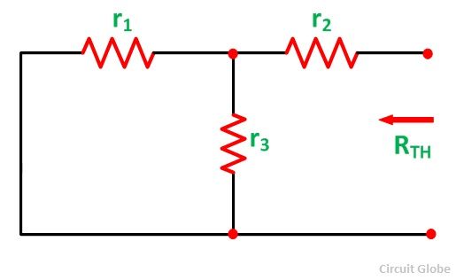
As per Thevenin’s Statement, the load current is determined by the circuit shown above and the equivalent Thevenin’s circuit is obtained.
The load current IL is given as:
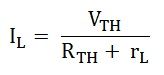
Where,
VTH is the Thevenin’s equivalent voltage. It is an open circuit voltage across the terminal AB known as load terminal
RTH is the Thevenin’s equivalent resistance, as seen from the load terminals where all the sources are replaced by their internal impedance
rL is the load resistance
Steps for Solving Thevenin’s Theorem
Step 1 – First of all remove the load resistance rL of the given circuit.
Step 2 – Replace all the sources by their internal resistance.
Step 3 – If sources are ideal then short circuit the voltage source and open circuit the current source.
Step 4 – Now find the equivalent resistance at the load terminals, known as Thevenin’s Resistance (RTH).
Step 5 – Draw the Thevenin’s equivalent circuit by connecting the load resistance and after that determine the desired response.
Video: Thevenin’s Theorem
This theorem is possibly the most extensively used networks theorem. It is applicable where it is desired to determine the current through or voltage across any one element in a network. Thevenin’s Theorem is an easy way to solve a complicated network.
Great work. very useful and educational article .
This website is very useful for students and science hobbyistics .
All contents are explained with concept.
Nice
Very thanks
Its helpful for students in examination..simple word to explanation
thanks a lot sir
Explained with complete clarity. Thanks.
Thank u so much
Thank you this information is very usefull to me
Thank you so much
Great explanation.