Norton’s Theorem states that – A linear active network consisting of the independent or dependent voltage source and current sources and the various circuit elements can be substituted by an equivalent circuit consisting of a current source in parallel with a resistance. The current source being the short-circuited current across the load terminal and the resistance being the internal resistance of the source network.
Contents:
The Norton’s theorems reduce the networks equivalent to the circuit having one current source, parallel resistance and load. Norton’s theorem is the converse of Thevenin’s Theorem. It consists of the equivalent current source instead of an equivalent voltage source as in Thevenin’s theorem.
The determination of internal resistance of the source network is identical in both the theorems.
In the final stage that is in the equivalent circuit, the current is placed in parallel to the internal resistance in Norton’s Theorem whereas in Thevenin’s Theorem the equivalent voltage source is placed in series with the internal resistance.
Explanation of Norton’s Theorem
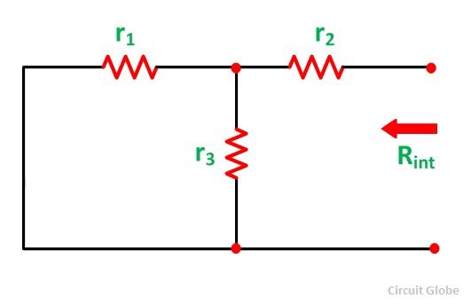
To understand Norton’s Theorem in detail, let us consider a circuit diagram given below
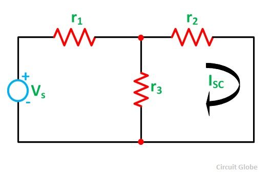
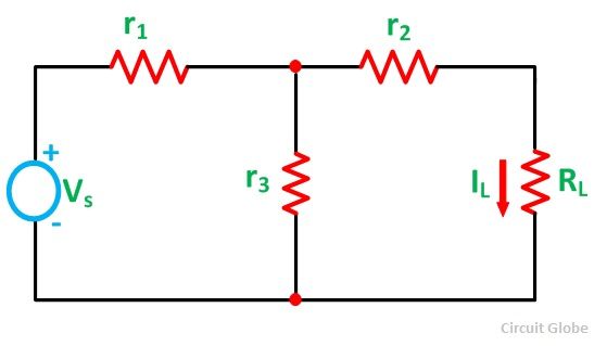 In order to find the current through the load resistance IL as shown in the circuit diagram above, the load resistance has to be short-circuited as shown in the diagram below:
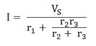
 Now, the value of current I flowing in the circuit is found out by the equation
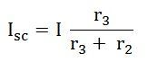
And the short-circuit current ISC is given by the equation shown below:
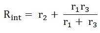
Now the short circuit is removed, and the independent source is deactivated as shown in the circuit diagram below and the value of the internal resistance is calculated by:
So,
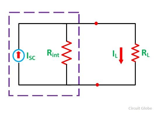
As per Norton’s Theorem, the equivalent source circuit would contain a current source in parallel to the internal resistance, the current source being the short-circuited current across the shorted terminals of the load resistor. The Norton’s Equivalent circuit is represented as
 Finally, the load current IL calculated by the equation shown below
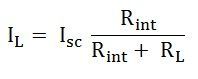
Where,
- IL is the load current
- Isc is the short circuit current
- Rint is the internal resistance of the circuit
- RL is the load resistance of the circuit
Steps for Solving a Network Utilizing Norton’s Theorem
Step 1 – Remove the load resistance of the circuit.
Step 2 – Find the internal resistance Rint of the source network by deactivating the constant sources.
Step 3 – Now short the load terminals and find the short circuit current ISC flowing through the shorted load terminals using conventional network analysis methods.
Step 4 – Norton’s equivalent circuit is drawn by keeping the internal resistance Rint in parallel with the short circuit current ISC.
Step 5 – Reconnect the load resistance RL of the circuit across the load terminals and find the current through it known as load current IL.
This is all about Norton’s Theorem.
good
I am thankful for your information
Thank you