The circuit containing only a pure capacitor of capacitance C farads is known as a Pure Capacitor Circuit. The capacitors stores electrical power in the electric field, their effect is known as the capacitance. It is also called the condenser.
The capacitor consists of two conductive plates which are separated by the dielectric medium. The dielectric material is made up of glass, paper, mica, oxide layers, etc. In pure AC capacitor circuit, the current leads the voltage by an angle of 90 degrees.
Contents:
- Explanation and derivation of Capacitor Circuit
- Phasor Diagram and Power Curve of Capacitor Circuit
- Power in Pure Capacitor Circuit
When the voltage is applied across the capacitor, then the electric field is developed across the plates of the capacitor and no current flow between them. If the variable voltage source is applied across the capacitor plates then the ongoing current flows through the source due to the charging and discharging of the capacitor.
Explanation and derivation of Capacitor Circuit
A capacitor consists of two insulating plates which are separated by a dielectric medium. It stores energy in electrical form. The capacitor works as a storage device, and it gets charged when the supply in ON and gets discharged when the supply is OFF. If it is connected to the direct supply, it gets charged equal to the value of the applied voltage.
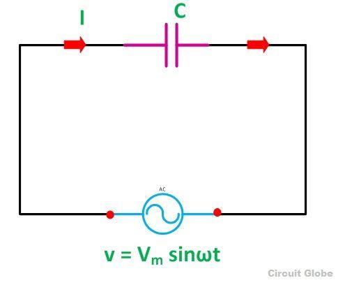
Let the alternating voltage applied to the circuit is given by the equation:
Charge of the capacitor at any instant of time is given as:
Current flowing through the circuit is given by the equation:
Putting the value of q from the equation (2) in equation (3) we will get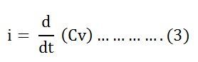
Now, putting the value of v from the equation (1) in the equation (3) we will get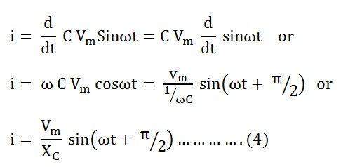
Where Xc = 1/ωC is the opposition offered to the flow of alternating current by a pure capacitor and is called Capacitive Reactance.
The value of current will be maximum when sin(ωt + π/2) = 1. Therefore, the value of maximum current Im will be given as: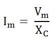
Substituting the value of Im in the equation (4) we will get: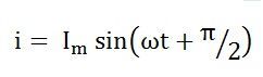
Phasor Diagram and Power Curve
In the pure capacitor circuit, the current flowing through the capacitor leads the voltage by an angle of 90 degrees. The phasor diagram and the waveform of voltage, current and power are shown below:
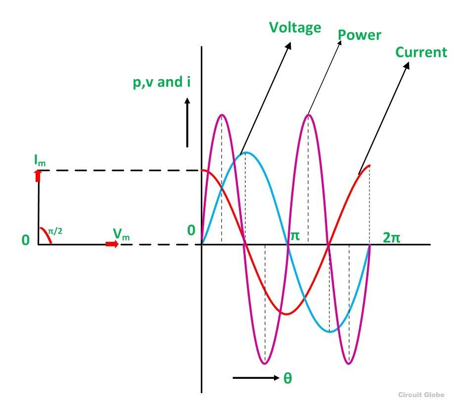
The red colour shows current, blue colour is for voltage curve, and the pink colour indicates a power curve in the above waveform.
When the voltage is increased, the capacitor gets charged and reaches or attains its maximum value and, therefore, a positive half cycle is obtained. Further when the voltage level decreases the capacitor gets discharged, and the negative half cycle is formed.
If you examine the curve carefully, you will notice that when the voltage attains its maximum value, the value of the current is zero that means there is no flow of current at that time.
When the value of voltage is decreased and reaches a value π, the value of voltage starts getting negative, and the current attains its peak value. As a result, the capacitor starts discharging. This cycle of charging and discharging of the capacitor continues.
The values of voltage and current are not maximised at the same time because of the phase difference as they are out of phase with each other by an angle of 90 degrees.
The phasor diagram is also shown in the waveform indicating that the current (Im) leads the voltage (Vm) by an angle of π/2.
Power in Pure Capacitor Circuit
Instantaneous power is given by p = vi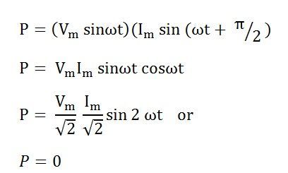
Hence, from the above equation, it is clear that the average power in the capacitive circuit is zero.
The average power in a half cycle is zero as the positive and negative loop area in the waveform shown are same.
In the first quarter cycle, the power which is supplied by the source is stored in the electric field set up between the capacitor plates. In the another or next quarter cycle, the electric field diminishes, and thus the power stored in the field is returned to the source. This process is repeated continuously and, therefore, no power is consumed by the capacitor circuit.
thats good stuff i had no problems in understanding the concepts , i appreciate the good work
Good work
Thank you
So much…
Very good concept l hope all students understand easily
Thank you. very understandable explanation..
Nic job
I really appreciate
Simple and good explanation. Clear and simple diagrams. Really good.
I have a question. A pure capacitance gets INSTANTLY charged or discharged because of the absence of any resistance. So if you connect a pure capacitance to an ac supply, the voltage across the capacitor plates would always be equal to the instantaneous value of the supply voltage, and hence the current in a purely capacitive circuit should always be zero. Where am I going wrong?