There are various types of transformer used in the electrical power system for different purposes, like generation, distribution and transmission and utilization of electrical power.
The different types of transformer are Step up and Step down Transformer, Power Transformer, Distribution Transformer, Instrument transformer comprising current and Potential Transformer, Single phase and Three phase transformer, Auto transformer, etc.
Contents:
- Step up and Stepdown Transformer
- Power Transformer
- Distribution Transformer
- Uses of Distribution Transformer
- Instrument Transformer
- Current Transformer
- Potential Transformer
- Single Phase Transformer
- Three Phase Transformer
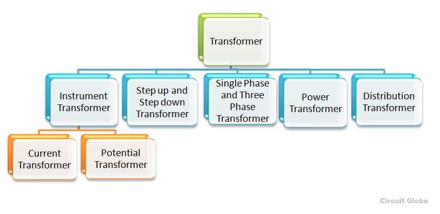
The various types of transformer shown in the figure above are explained in detail below.
Step up and Step down Transformer
This type of transformer is categorized on the basis of a number of turns in the primary and secondary windings and the induced emf.
Step-up transformer transforms a low voltage, high current AC into a high voltage, low current AC system In this type of transformer the number of turns in the secondary winding is greater than the number of turns in the primary winding. If (V2 > V1) the voltage is raised on the output side and is known as Step-up transformer
Step down transformer converts a high primary voltage associated with the low current into a low voltage, high current. With this type of transformer, the number of turns in the primary winding is greater than the number of turns in the secondary winding. If (V2 < V1) the voltage level is lowered on the output side and is known as Step down transformer
Power Transformer
The power transformers are used in the transmission networks of higher voltages. The ratings of the power transformer are as follows 400 KV, 200 KV, 110 KV, 66 KV, 33 KV. They are mainly rated above 200 MVA. Mainly installed at the generating stations and transmission substations. They are designed for maximum efficiency of 100%. They are larger in size as compared to the distribution transformer.
At a very high voltage, the power cannot be distributed to the consumer directly, so the power is stepped down to the desired level with the help of step-down power transformer. The transformer is not loaded fully hence the core loss takes place for the whole day, but the copper loss is based on the load cycle of the distribution network.
If the power transformer is connected in the transmission network, the load fluctuation will be very less as they are not connected at the consumer end directly, but if connected to the distribution network there will be fluctuations in the load.
The transformer is loaded for 24 hours at the transmission station, thus, the core and copper loss will occur for the whole day. The power transformer is cost-effective when the power is generated at low voltage levels. If the level of voltage is raised, then the current of the power transformer is reduced, resulting in I2R losses and the voltage regulation is also increased.
Distribution Transformer
This type of transformer has lower ratings like 11 KV, 6.6 KV, 3.3 KV, 440 V and 230 V. They are rated less than 200 MVA and used in the distribution network to provide voltage transformation in the power system by stepping down the voltage level where the electrical energy is distributed and utilized at the consumer end.
The primary coil of the distribution transformer is wound by enamel coated copper or aluminum wire. A thick ribbon of aluminum and copper is used to make secondary of the transformer which is a high current, low voltage winding. Resin impregnated paper and oil is used for the insulation purpose.
The oil in the transformer is used for
- Cooling
- Insulating the windings
- Protecting from the moisture
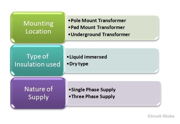
The various types of the distribution transformer are categorized on the following basis and are shown in the figure below
- Mounting location
- Type of insulation
- Nature of supply
The distribution transformer less than 33 KV is used in industries and 440, 220 V is used for the domestic purpose. It is smaller in size, easy to install and has low magnetic losses and is not always loaded fully.
As it does not work for constant load throughout 24 hours as in the daytime its load is at its peak, and during the night hours it is very lightly loaded thus the efficiency depends on load cycle and is calculated as All Day Efficiency. The distribution transformers are designed for maximum efficiency of 60 to 70%
Uses of Distribution Transformer
- Used in pumping stations where the voltage level is below 33 KV
- Power supply for the overhead wires railways electrified with AC
- In urban areas, many houses are fed with single-phase distribution transformer and in rural areas, it may be possible that one house requires one single transformer depending upon the loads.
- Multiple distribution transformers are used for industrial and commercial areas.
- Used in wind farms where the electrical energy is generated by the windmills. There it is used as a power collector to connect the substations which are away from the wind energy generation system.
Instrument Transformer
- They are generally known as an isolation transformer. Instrument transformer is an electrical device used to transform current as well as a voltage level. The most common use of instrument transformer is to safely isolate the secondary winding when the primary has high voltage and high current supply so that the measuring instrument, energy meters or relays which are connected to the secondary side of the transformer will not get damaged. The instrument transformer is further divided into two types
- Current Transformer (CT)
- Potential Transformer (PT)
The current and potential transformer is explained below in detail
Current Transformer
-
- The current transformer is used for measuring and also for the protection. When the current in the circuit is high to apply directly to the measuring instrument, the current transformer is used to transform the high current into the desired value of the current required in the circuit.
- The primary winding of the current transformer is connected in series to the main supply and the various measuring instruments like ammeter, voltmeter, wattmeter or protective relay coil. They have accurate, current ratio and phase relation to enable the meter accurately on the secondary side. The term ratio has a great significance in CT.
- For example, if its ratio is 2000:5, it means a CT has an output of 5 Ampere when the input current is 2000 amp on the primary side. The accuracy of the Current Transformer depends upon many factors like Burden, load, temperature, phase change, rating, saturation, etc.
- In the current transformer, the total primary current is the vector sum of the excitation current and the current equal to the reversal of secondary current multiplied by turn ratio.
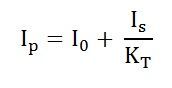
Where,
Ip – primary current
Is – secondary or reversal current
I0 – excitation current
KT – turn ratio
Potential Transformer
The potential transformer is also called as the voltage transformer. The primary winding is connected across the High voltage line whose voltage is to be measured, and all the measuring instruments and meters are connected to the secondary side of the transformer.
The main function of the Potential transformer is to step down the voltage level to a safe limit or value. The primary winding of the potential transformer is earthed or grounded as a safety point.
For example, the voltage ratio primary to secondary is given as 500:120, it means the output voltage is of 120 V when the 500 V is applied to the primary. The different types of potential transformer are shown below in the figure
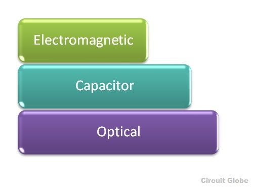
- Electromagnetic (it is a wire wound transformer)
- Capacitor (capacitor voltage transformer CVT uses capacitor voltage divider)
- Optical (works on the electrical property if optical materials)
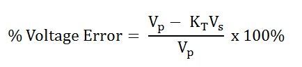
The percentage voltage error is given by the equation shown below
Single Phase Transformer
A single-phase transformer is a static device, works on the principle of Faraday’s law of mutual Induction. At a constant level of frequency and variation of voltage level, the transformer transfers AC power from one circuit to the other circuit. There are two types of windings in the transformer. The winding to which AC supply is given is termed as Primary winding and in the secondary winding, the load is connected.
Three Phase Transformer
If the three single-phase transformer is taken and connected together with their all the three primary winding connected to each other as one and all the three secondary windings to each other, forming as one secondary winding, the transformer is said to behave as a three-phase transformer, that means a bank of three single-phase transformer connected together which acts as a three-phase transformer.
Three-phase supply is mainly used for electric power generation, transmission and distribution for industrial purpose. It is less costly to assemble three single-phase transformer to form a three-phase transformer than to purchase one single three-phase transformer. The three-phase transformer connection can be done by Star (Wye) and Delta (Mesh) type.
The connection of primary and secondary winding can be done by various combinations shown below
| Primary Winding | Secondary Winding |
|---|---|
| Star (Wye) | Star |
| Delta (mesh) | Delta |
| Star | Delta |
| Delta | Star |
The combination of the primary winding and the secondary winding is done as star-star, delta-delta, star-delta and delta-star.
Hey,
Transformers which share a winding or a portion of a winding are called?
A. Step down transformers
B. Step up transformers
C. Auto transformers?
D. Neutral transformers?
Auto Transformers.
Thanks.
Why Transformer Rated in KVA
To know about the rating of the transformer, you may refer the following links.
For English version:-
https://www.youtube.com/watch?v=vnX0Re2z_8A
For Hindi version:-
https://www.youtube.com/watch?v=Rooz8EgsQvc
One of the reasons is that there are 2 major losses in a transformer : load loss which depends on current(A) and no-load loss which depends on voltage(V)
bcz its rated speed is constant
Because the losses which occurred in a transformer are measured as Volt-Ampere….
Transformer rating in kva becouse the losses in transfomer determined by V and I
Core loss – V
Copper loss – I
Thanks for helping me understand that a current transformer will be able to change the current from high to the desired value. I have been really curious about this because my uncle has been talking about buying a split core current transformer for the second-hand AC units that he bought. He has been studying how to fix them to open up a business soon.
What sort of transformer do I need to create a phantom/virtual load?
Large distribution,small,medium also inslude in types of transformer? If yes some one explain me
really good information keep up the good work
very nicely written and good information
WoW I enjoyed reading this
Great
Your article helped me to win the quiz…….Thank you so much
Wonderful ideas about transformers
Keep working and God bless you.
Thank you for your help.