The Synchronous Impedance Method or Emf Method is based on the concept of replacing the effect of armature reaction with an imaginary reactance. For calculating the regulation, the synchronous method requires the following data; they are the armature resistance per phase and the open-circuit characteristic. The open-circuit characteristic is the graph of the circuit voltage and the field current. This method also requires a short circuit characteristic which is the graph of the short circuit and the field current.
Contents:
- DC resistance test
- Open Circuit Test
- Short Circuit Test
- Calculation of Synchronous Impedance
- Assumptions in the Synchronous Impedance Method
For a synchronous generator following are the equation given below:![]()
Where,![]()
For calculating the synchronous impedance, Zs is measured, and then the value of Ea is calculated. From the values of Ea and V, the voltage regulation is calculated.
Measurement of Synchronous Impedance
The measurement of synchronous impedance is done by the following methods. They are known as:
- DC resistance test
- Open circuit test
- Short circuit test
DC resistance test
In this test, it is assumed that the alternator is star connected with the DC field winding open as shown in the circuit diagram below:
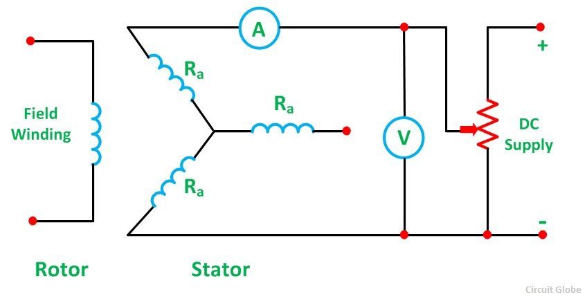 It measures the DC resistance between each pair of terminals either by using an ammeter – voltmeter method or by using the Wheatstone’s bridge. The average of three sets of resistance value Rt is taken. The value of Rt is divided by 2 to obtain a value of DC resistance per phase. Since the effective AC resistance is larger than the DC resistance due to skin effect. Therefore, the effective AC resistance per phase is obtained by multiplying the DC resistance by a factor 1.20 to 1.75 depending on the size of the machine. A typical value to use in the calculation would be 1.25.
Open Circuit Test
In the open-circuit test for determining the synchronous impedance, the alternator is running at the rated synchronous speed, and the load terminals are kept open. This means that the loads are disconnected, and the field current is set to zero. The circuit diagram is shown below:
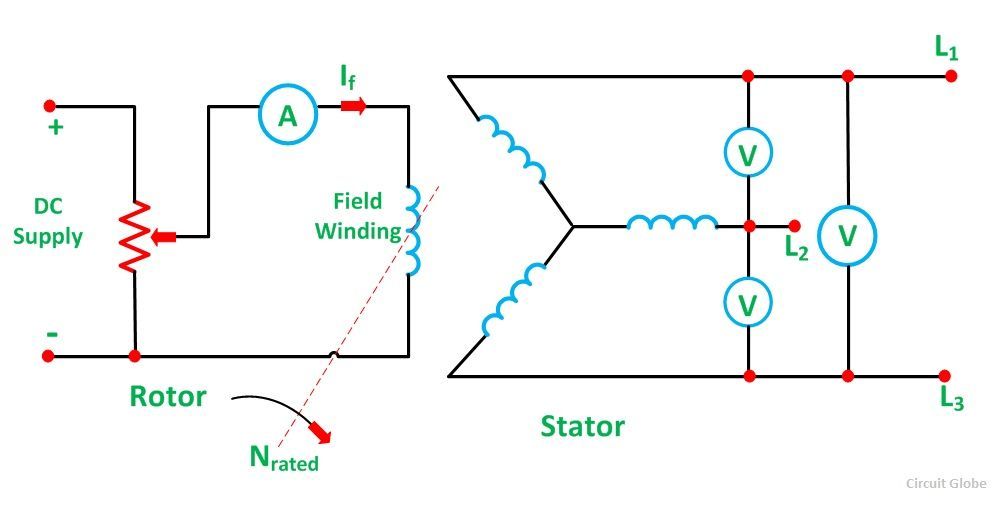 After setting the field current to zero, the field current is gradually increased step by step. The terminal voltage Et is measured at each step. The excitation current may be increased to get 25% more than the rated voltage. A graph is drawn between the open circuit phase voltage Ep = Et/√3 and the field current If. The curve so obtained called Open Circuit Characteristic (O.C.C). The shape is the same as the normal magnetization curve. The linear portion of the O.C.C is extended to form an air gap line.
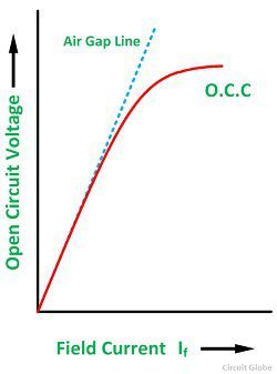
The Open Circuit Characteristic (O.C.C) and the air gap line is shown in the figure below:
Short Circuit Test
In the short circuit test, the armature terminals are shorted through three ammeters as shown in the figure below:
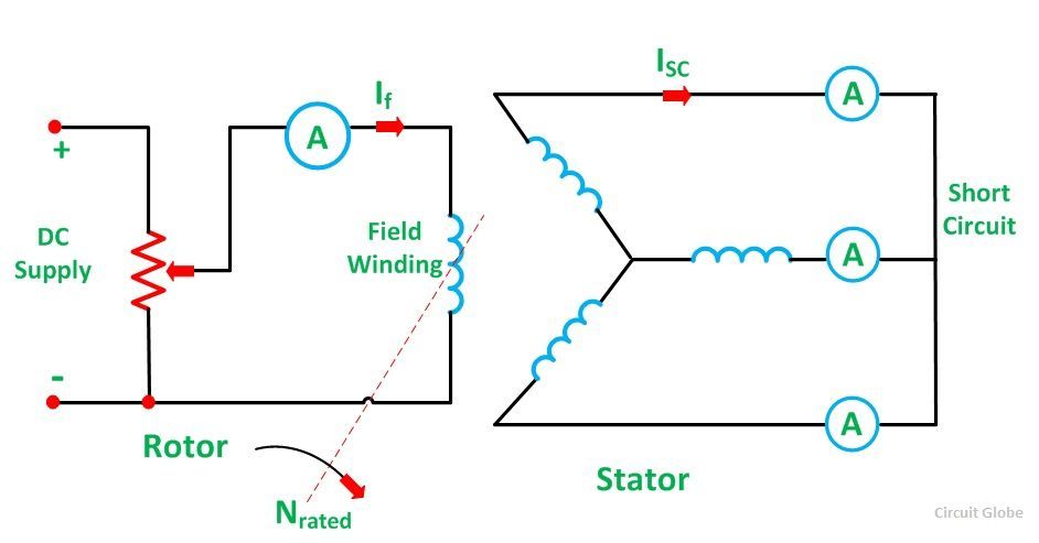 The field current should first be decreased to zero before starting the alternator. Each ammeter should have a range greater than the rated full load value. The alternator is then run at synchronous speed. Same as in an open circuit test that the field current is increased gradually in steps and the armature current is measured at each step. The field current is increased to get armature currents up to 150% of the rated value.
The value of field current If and the average of three ammeter readings at each step is taken. A graph is plotted between the armature current Ia and the field current If. The characteristic so obtained is called Short Circuit Characteristic (S.C.C). This characteristic is a straight line as shown in the figure below.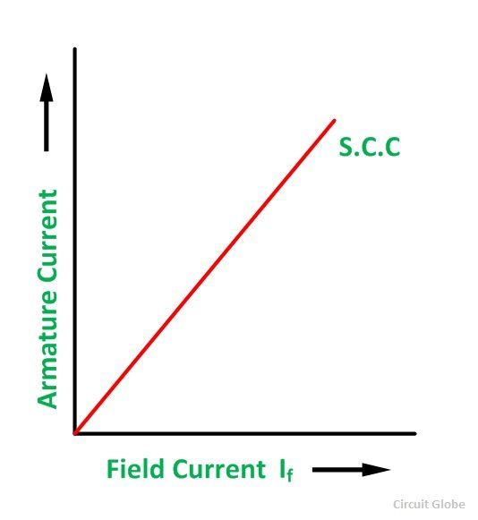
Calculation of Synchronous Impedance
The following steps are given below for the calculation of the synchronous impedance.
- The open-circuit characteristics and the short circuit characteristic are drawn on the same curve.
- Determine the value of short circuit current Isc and gives the rated alternator voltage per phase.
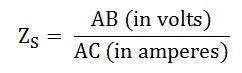
- The synchronous impedance ZS will then be equal to the open-circuit voltage divided by the short circuit current at that field current which gives the rated EMF per phase.
 The synchronous reactance is determined as
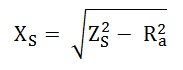
The graph is shown below:
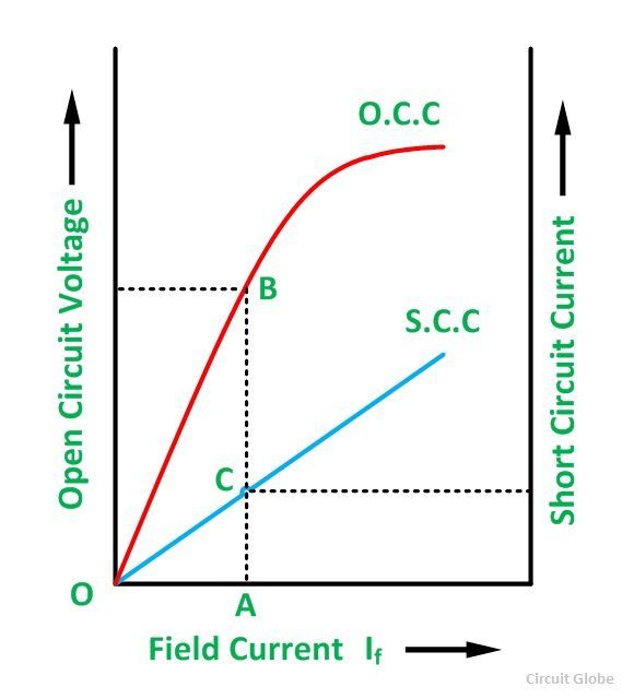 From the above figure consider the field current If = OA that produces rated alternator voltage per phase. Corresponding to this field current, the open-circuit voltage is AB
Assumptions in the Synchronous Impedance Method
The following assumptions made in the synchronous Impedance Method are given below:
- The synchronous Impedance is constant
The synchronous impedance is determined from the O.C.C and S.C.C. It is the ratio of the open-circuit voltage to the short circuit current. When the O.C.C and S.C.C are linear, the synchronous impedance ZS is constant.
- The flux under test conditions is the same as that under load conditions.
It is assumed that a given value of the field current always produces the same flux. This assumption introduces considerable error. When the armature is short circuited, the current in the armature lag the generated voltage by almost 90 degrees, and hence the armature reaction is almost completely demagnetizing.
- The effect of the armature reaction flux can be replaced by a voltage drop proportional to the armature current and that the armature reaction voltage drop is added to the armature reactance voltage drop.
- The magnetic reluctance to the armature flux is constant regardless of the power factor.
For a cylindrical rotor machine, this assumption is substantially true because of the uniform air gap. Regulation obtained by using a synchronous impedance method is higher than that obtained by actual loading. Hence, this method is also called the Pessimistic method.
At lower excitations, ZS is constant, since the open circuit characteristics coincide with the air gap line. This value of ZS is called the linear or Unsaturated Synchronous Impedance. However, with increasing excitation, the effect of saturation is to decrease ZS and the values beyond the linear part of the open circuit called as Saturated Value of the Synchronous Impedance.
It’s clear my concept about occ and scc of synchronous machine
Very helpful article… It answered my assignment questions
It is very useful to me for my exams
How can we take the values of voltage and current for finding Z value from graph.
I lost my notes ..and this was very helpful for me in this situation ..thank you so much