MMF Method is also known as Ampere Turn Method. The synchronous impedance method is based on the concept of replacing the effect of armature reaction with an imaginary reactance, the Magnetomotive force (MMF). The MMF method replaces the effect of armature leakage reactance with an equivalent additional armature reaction MMF so that this MMF may be combined with the armature reaction MMF.
To calculate the voltage regulation by MMF Method, the following information is required. They are as follows:
- The resistance of the stator winding per phase.
- Open circuit characteristics at synchronous speed.
- Short circuit characteristic
Step to Draw Phasor Diagram of MMF Method
The phasor diagram at a lagging power factor is shown below:
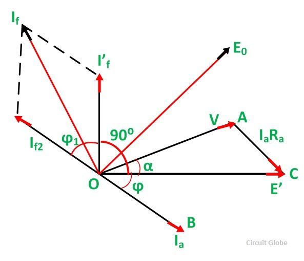
- The armature terminal voltage per phase (V) is taken as the reference phasor along OA.
- The armature current phasor Ia is drawn lagging the phasor voltage for lagging power factor angle ϕ for which the regulation is to be calculated.
- The armature resistance drop phasor IaRa is drawn in phase with Ia along the line AC. Join O and C. OC represents the emf E’.
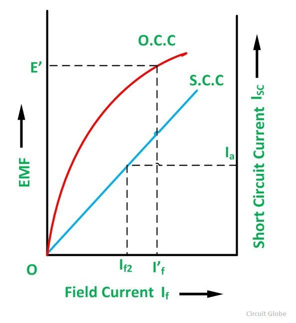
- Considering the open current characteristics shown above the field current I’f corresponding to the voltage E’ is calculated.
- Draw the field current I’f leading the voltage E’ by 90 degrees. It is assumed that on a short circuit all the excitation is opposed by the MMF of armature reaction. Thus,
![]() From the short circuit current characteristics (SSC) shown above, determine the field current If2 required to circulate the rated current on short circuit. This is the field current required to overcome the synchronous reactance drop IaXa.
From the short circuit current characteristics (SSC) shown above, determine the field current If2 required to circulate the rated current on short circuit. This is the field current required to overcome the synchronous reactance drop IaXa.
- Draw the field current If2 in phase in opposition to the current armature current Ia. Thus,
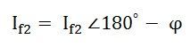
Determine the phasor sum of the field currents I’f and If2. This gives the resultant field current If which would generate a voltage E0 under no-load conditions of the alternator. The open-circuit emf E0 corresponding to the field current if is found from the open circuit characteristics.
The regulation of the alternator is found from the relation shown below:
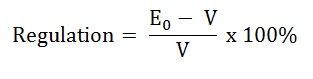
This is all about MMF method of voltage regulation.
good
gud one
Please tell me
This is also known as Rother mmf method?
Yes