Definition: The bridge which measures the inductance in terms of capacitance is known as Owen’s bridge. It works on the principle of comparison i.e., the value of the unknown inductor is compared with the standard capacitor. The connection diagram of Owen’s bridge is shown in the figure.
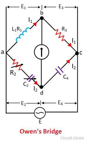 The ab, bc, cd and da are the four arms of Owen’s bridge. The arms ab are purely inductive and the arm bc is purely resistive in nature. The arm cd has fixed capacitor and the arm ad consists the variable resistor and capacitor connected in series with the circuit.
The unknown inductor L1 of arm ab is compared with the known capacitor C4 connected to the arm cd. The bridge is kept in balanced condition by independently varying the resistor R2 and the capacitor C2. At the balanced condition, no current flows through the detector. The end points (b and c) of the detector are at the same potential.
Phasor Diagram of Owen’s Bridge
The phasor diagram of Owen’s bridge is shown in the figure below.
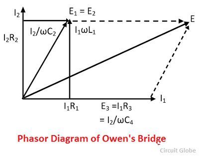
The current I1, E3 = I3R3 and E4 = ωI2C4 are all on the same phases and are represented on the horizontal axis. The voltage drop I1R1 in the arm ab is also represented on the horizontal axis.
The sum of the inductive voltage drop ωL1I1 and the resistive voltage drop I1R1 gives the voltage drop E1 of the arm ab. When the bridge is in the balanced condition the potential E1 and E2 across the arm ab and ad are equal. Thus, it is shown on the same axis.
The voltage drop V2 is the summation of the resistive voltage drop I2R2 and capacitive voltage drop I2/wC2. The I2 of the arm ad lead by 90º with the voltage drop V4 of the arm cd because of the fixed capacitor C4.
The current I2 and the voltage I2R2 are represented on the vertical phases shown in the figure above. The supply voltage is obtained by adding the voltage V1 and V3.
Theory of Owen’s Bridge
Let, L1 – unknown self-inductance of resistance R1
R2 – variable non-inductive resistance
R3 – fixed non-inductive resistance
C2 – variable standard capacitor
C4 – fixed standard capacitor
At balance condition, 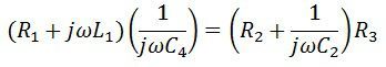
On separating the real and imaginary part we get,
![]()
And, 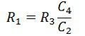
Advantages of Owen’s Bridge
The following are the advantages of Owen’s bridge.
- The balance equation is easily obtained.
- The balance equation is simple and does not contain any frequency component
- The bridge is used for the measurement of the large range inductance.
Disadvantages of Owen’s Bridge
- The bridge uses an expensive capacitor which increases the cost of the bridge and also it gives a one percent accuracy.
- The value of the fixed capacitor C2 is much larger than the quality factor Q2
The Owen’s bridge is modified by connecting the voltmeter in parallel with the resistive arms of the bridge. The direct and alternating both the supply is given to the bridges. The ammeter is connected in series with the bridge for measuring the DC current. and the alternating current is measured by the help of voltmeter.
Thanks it is very helpful to me.
please give me about de sauty bridge
Please give suggestions about quality factor measure by Owens bridge.
superb
Very helpful for me.
Thanks, I was able to derive the equation by myself.