No Load Test is an indirect method used for determining the efficiency and also to determine the circuit parameters of the equivalent circuit of the three-phase induction motors. The open-circuit test is performed on the transformer. The no-load test is the same as the open-circuit test performed on the transformer.
In this method, the motor is uncoupled from its load and the rated voltage at the rated frequency is applied to the stator to run the motor without the load. With the help of the two wattmeters, the input power of the motor is measured. The circuit diagram of the No-load test is shown below:
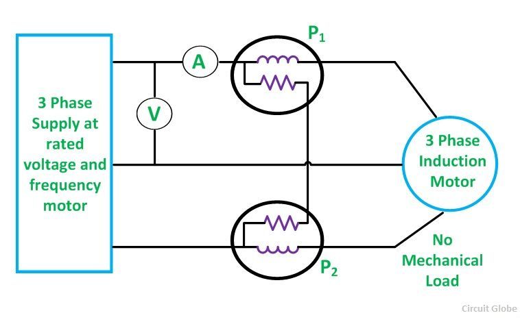 An ammeter measures the no-load current, and a voltmeter gives the normal rated supply voltage. The I2R losses on the primary side are neglected as they vary with the square of the current, as we know that the no-load current is 20-30% of the full load current,
As the motor is running at no load, the total input power is equal to the constant iron loss, friction, and windage losses of the motor. Since the power factor of the induction motor under no-load condition is generally less than 0.5, thus the Wattmeter reading of one of the Wattmeter will show a negative reading. Therefore, it is necessary to reverse the direction of the current coil terminals to take the readings.
In the case of the transformer, no-load test the constant R0 and X0 can be calculated from the readings of the test.
If,
- Vinl is the input line voltage,
- Pinl is the total three-phase input power at the no load,
- I0 is the input line current,
- Vip is the input phase voltage.
Therefore,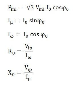
Separation of Losses
Friction and windage loss can be separated from the no-load loss P0. At no load, various readings of the no-load loss are taken at the different stator applied voltages. The readings are taken from rated to the breakdown value at rated frequency.
A curve plotted between P0 and V is shown below:
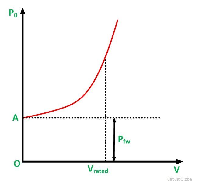 The curve is almost parabolic at the normal voltage. As the iron losses are almost proportional to the square of the flux density and therefore, the applied voltage. The curve is extended to the left to cut the vertical axis at the point A. At the vertical axis V = 0 and hence the intercept OA represents the independent voltage loss. This means the friction and the windage losses are separated from the total no-load loss.
FOR STATOR COPPER LOSS WHY CURRENT I IS DIVIDED BY ROOT THREE ???
shall i use digital watt meter
Great article.