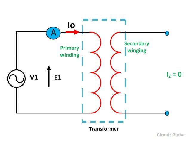
When the transformer is operating at no load, the secondary winding is open-circuited, which means there is no load on the secondary side of the transformer and, therefore, current in the secondary will be zero. While primary winding carries a small current I0 called no-load current which is 2 to 10% of the rated current.
This current is responsible for supplying the iron losses (hysteresis and eddy current losses) in the core and a very small amount of copper losses in the primary winding. The angle of lag depends upon the losses in the transformer. The power factor is very low and varies from 0.1 to 0.15.
 The no-load current consists of two components:
- Reactive or magnetizing component Im
(It is in quadrature with the applied voltage V1. It produces flux in the core and does not consume any power).
- Active or power component Iw, also know as a working component
(It is in phase with the applied voltage V1. It supplies the iron losses and a small amount of primary copper loss).
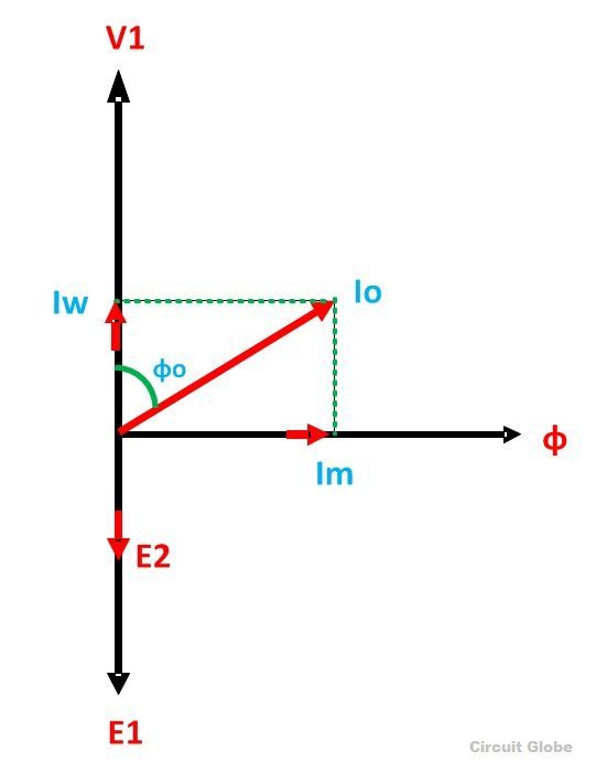
The following steps are given below to draw the phasor diagram:
- The function of the magnetizing component is to produce the magnetizing flux, and thus, it will be in phase with the flux.
- Induced emf in the primary and the secondary winding lags the flux ϕ by 90 degrees.
- The primary copper loss is neglected, and secondary current losses are zero as
I2 = 0.
Therefore, the current I0 lags behind the voltage vector V1 by an angle ϕ0 called the no-load power factor angle and is shown in the phasor diagram above. - The applied voltage V1 is drawn equal and opposite to the induced emf E1 because the difference between the two, at no load, is negligible.
- Active component Iw is drawn in phase with the applied voltage V1.
- The phasor sum of magnetizing current Im and the working current Iw gives the no-load current I0.
 From the phasor diagram drawn above, the following conclusions are made:
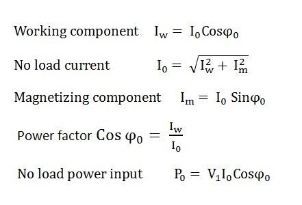
This is all about transformer in no load condition.
How The Magnetizing Component (Im) can be minimised as done in Case of Motor By Capacitor Bank ????????????????………..
This Will Give relief From Paying Extra .
REply Requested
We can minimize it by using high permeability core material.this is the region why we are using CRGO steel in transformer.
Why some transformers exitation current are low and why some are high.What is the required range subject their KVA rating.