The Schering bridge use for measuring the capacitance of the capacitor, dissipation factor, properties of an insulator, capacitor bushing, insulating oil and other insulating materials. It is one of the most commonly used AC bridge. The Schering bridge works on the principle of balancing the load on its arm.
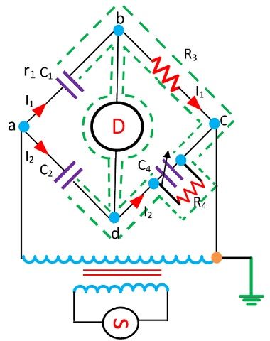
Let, C1 – capacitor whose capacitance is to be determined,
r1 – a series resistance, representing the loss of the capacitor C1.
C2 – a standard capacitor (The term standard capacitor means the capacitor is free from loss)
R3 – a non-inductive resistance
C4 – a variable capacitor.
R4 – a variable non-inductive resistance parallel with variable capacitor C4.
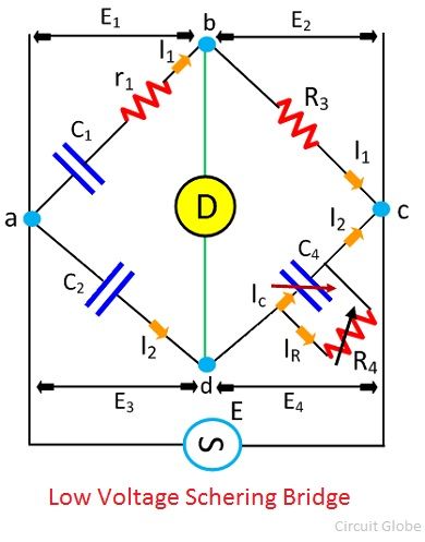 When the bridge is in the balanced condition, zero current passes through the detector, which shows that the potential across the detector is zero. At balance condition
Z1/Z2 = Z3/Z4
Z1Z4 = Z2Z3
So,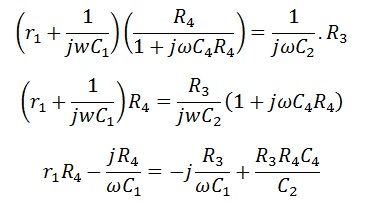 Equating the real and imaginary equations, we get
 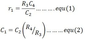 The equation (1) and (2) are the balanced equation, and it is free from the frequency.
The dissipation factor obtains with the help of the phasor diagram. The dissipation factor determines the rate of loss of energy that occurs because of the oscillations of the electrical and mechanical instrument.
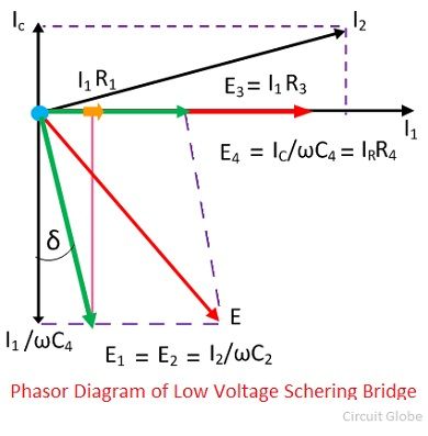
 By the help of the above equation, we can calculate the value of tanδ which is the dissipation factor of the Schering bridge.
Advantages of Schering Bridge
The following are the advantages of the Schering bridge.
- Balance equations are free from frequency.
- The arrangement of the bridge is less costly as compared to the other bridges.
High Voltage Schering Voltage
The low voltage Schering bridge has several disadvantages, and because of this reason, the high voltage and high frequency are required for measuring the small capacitance. The circuit diagram of the Schering bridge is shown in the figure below.
 The following are the features of the Schering Bridge.
- The high voltage supply obtains from the operational amplifier. The vibration galvanometer use as a detector for the bridge.
- The high voltage working capacitors are placed in the arms ab and ad. The impedance of the arm ab and ad are very high as compared to the arm bc and cd. The term impedance means the opposition offered by the circuit in the flow of current. The point c is earthed.
- The impedance of the arm ab and ad is kept high so that the high supply will not affect the potential across the arm bc and cd. The potential across the detector is also kept low.
- The spark gap sets places on each arm for preventing the dangerous high voltage which appears across the arm bc and dc because of the breakdown of the high voltage capacitors.
- The power loss is very small in the arms ab and ad because of the high impedance of arms ab and ad.
Measurement of Relative Permeability with Schering Bridge
The Schering bridge use for measuring the low permeability of the dielectric material. The relative permeability shows the ability of the material for the formation of the magnetic field. It is calculated with the help of the capacitance and dimension of the electrodes.
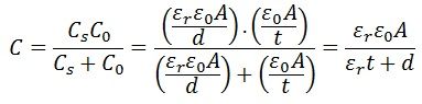
The relative permeability of the parallel plate arrangement is expressed as
 Cs – the measured value of capacitance by considering the specimen as a dielectric.
d – Spacing between electrodes
A – Effective area of electrodes.
ε0 – permittivity of free space
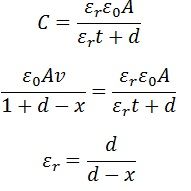
The other method for calculating the relative permittivity of the specimen is explained below.
The relative permittivity of the specimen depends on the thickness of the specimen and the spacing between them and the electrode.
Let, C – capacitance between the electrode and specimen
A – area of electrodes
d – the thickness of the specimen
t – the gap between specimen and electrode.
x – reduction in separation between the specimen and electrode.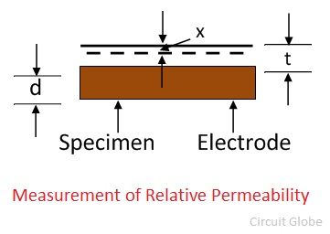 Cs – capacitance of specimen.
C0 – Capacitance between the space because of specimen and electrode.
C – effective capacitance of Cs and C0.
The capacitance between the specimen and the electrode is expressed as
 When we reduce the specimen and the spacing is again adjusted for obtaining the same value of capacitance, the expression for reducing specimen is.
 The insulating properties of electrical cables and equipment can also be measured through the Schering bridge.