Definition – The resistance thermometer or resistance temperature detector (RTD) uses the resistance of electrical conductor for measuring the temperature. The resistance of the conductor varies with the time. This property of the conductor is used for measuring the temperature. The main function of the RTD is to give a positive change in resistance with temperature.
The metal has a high-temperature coefficient that means their temperature increases with the increase in temperature. The carbon and germanium have low-temperature coefficient which shows that their resistance is inversely proportional to temperature.
Material used in Resistive Thermometer
The resistance thermometer uses a sensitive element made of extremely pure metals like platinum, copper or nickel. The resistance of the metal is directly proportional to the temperature. Mostly, platinum is used in resistance thermometer. The platinum has high stability, and it can withstand high temperature.
Gold and silver are not used for RTD because they have low resistivity. Tungsten has high resistivity, but it is extremely brittles. The copper is used for making the RTD element. The copper has low resistivity and also it is less expensive. The only disadvantage of the copper is that it has low linearity. The maximum temperature of the copper is about 120ºC.
The RTD material is made of platinum, nickel or alloys of nickel. The nickel wires are used for a limited temperature range, but they are quite nonlinear.
The following are the requirements of the conductor used in the RTDs.
- The resistivity of the material is high so that the minimum volume of conductor is used for construction.
- The change in resistance of the material concerning temperature should be as high as possible.
- The resistance of the material depends on the temperature.
The resistance versus temperature curve is shown in the figure below. The curves are nearly linear, and for small temperature range, it is very evident.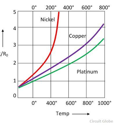
Construction of Resistive Thermometer
The resistance thermometer is placed inside the protective tube for providing the protection against damage. The resistive element is formed by placing the platinum wire on the ceramic bobbin. This resistance element is placed inside the tube which is made up of stainless steel or copper steel.
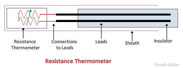
The lead wire is used for connecting the resistance element with the external lead. The lead wire is covered by the insulated tube which protects it from short circuit. The ceramic material is used as an insulator for high-temperature material and for low-temperature fibre or glass is used.
Operation of Resistance Thermometer
The tip of the resistance thermometer is placed near the measurand heat source. The heat is uniformly distributed across the resistive element. The changes in the resistance vary the temperature of the element. The final resistance is measured. The below mention equations measure the variation in temperature.
![]()
Where, R0 – resistance at temperature T = 0 and α1, α2, α3……..αn are constants.
Linear Approximation
The linear approximation is the way of estimating the resistance versus temperature curve in the form of the linear equation.![]()
where Rθ – approximation resistance at θºC
Rθ0 – approximation resistance at θ0ºC
Δθ – θ – θ0 change in temperature ºC and the αθ0 – resistance temperature coefficient at θ0ºC
Quadratic Approximation
The quadratic approximation gives the accurate approximation of the resistance temperature curve. The approximation is expressed in the form of the quadratic equation.![]()
α1 – linear fractional change in resistance
α2 – quadratic function change in resistance.
The resistance thermometer is very less sensitive, and the metal used for making the resistive element is less expensive.