Definition: Feeder protection is defined as the protection of the feeder from the fault so that the power grid continue supply the energy. The feeder injects the electrical energy from the substation to the load end. So it is essential to protect the feeder from the various type of fault. The main requirement of the feeder protection are;
- During the short circuit, the circuit breaker nearest to the fault should open and all other circuit breakers remain in a closed position.
- If the breaker nearest to the fault fails to open then, backup protection should be provided by the adjacent circuit breaker.
- The relay operating time should be small to maintain the system stability without necessary tripping of a circuit.
Time Graded Protection
This is a scheme in which the time setting of relays is so consecutive that in the event of a fault, the smallest possible part of the system is isolated. The applications of time graded are explained below.
Protection of Radial Feeders
The main characteristic of a radial system is that power flow only in one direction, i.e. from the generator or the supply end to the load end. It has the drawback that continuity of supply cannot be controlled at the load end in the occurrence of a fault.
In a radial system when the number of feeders is connected in series as shown in the figure. It is desired that the smallest possible part of the system should be off. This is conveniently achieved by employing time graded protection. The over current system should be adjusted in such a way that the longer the relay from the generating station the lesser the time of operation.
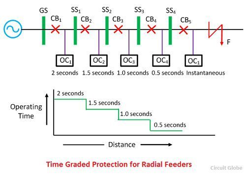 When the fault occurs on the SS4, the relay OC5 should operate first and not any other i.e. the time require to operate the relay OC4 must be less than the time required for relay OC3 and so on. This shows that the time setting required for these relays must be properly graded. The minimum interval of time which can be allowed for the two adjacent circuit breaker depends on its own clearance time, plus a small time for the safety margin.
With normal circuit breaker in use minimum, the discriminating time between adjustment breaker should be about 0.4 seconds. The time settings for relay OC1, OC2, OC3, OC4, and OC5 will be 0.2 seconds, 1.5 seconds, 1.5 seconds, 1.0 seconds, 0.5 second and instantaneous respectively. Along with the grading system, it is also essential that the time of operation for the severe fault should be less. This can be done by using time limiting fuse in parallel with the trip coils.
Protection of Parallel Feeders
The parallel connection of the supply is mainly used for the continuity of the supply and for sharing the load. When the fault occurs on the protective feeder, the protective device will select and isolate the defective feeder while the other instantly assume the increased load.
One of the simplest methods for the protection of the relay is the time graded overload relay with inverse time characteristic at the sending end and instantaneous reverse power or directional relays at the receiving end as shown in the figure below.
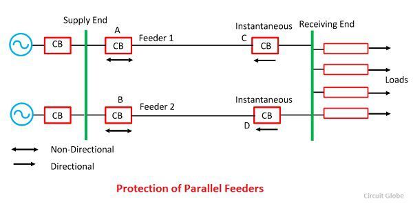 When the heavy fault F occur on any one of the lines, then the power is fed into fault from the sending end as well as from the receiving end of the line. The direction of power flow will be reversed through the relay on D, which will be open.
The excess current is then restricted to B until its overload relay operates and trips the circuit breaker, thus completely isolating the faulty feeder and supplying power through the healthy feeder. This method is only satisfactory when the fault is heavy and reverse the power at D. Hence differential protection is also added along with the overloaded protection at both the end of the line.
Protection of Ring Main System
The ring main is a system of interconnection between a series of the power station by a different route. In the main ring system, the direction of power can be changed at will, particularly when the interconnection is used.
The elementary diagram of such a system is shown in the figure below where G is the generating station, and A, B, C, and D are substation. At the generating station, the power flow only in one direction and hence no time lag overload relays is used. The time grade overload relay is placed at the end of the substation, and it will trip only when overload flows away from the substation which they protect.
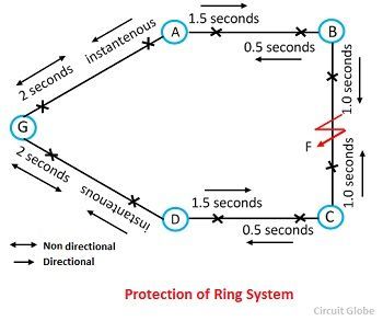 Going round the ring in the direction GABCD the relay on the further side of each station are set with decreasing time lags. At generating station 2 seconds at station A, B, C and 1.5 seconds, 1.0 second, 0.5 second and instantaneous respectively. Similarly going round the ring in the opposite direction the relay on the outgoing sides would be set as follows.
If the fault occurs at point F, the power F is fed into the fault through two paths ABF and DCF. The relay to operate is that between substation B and fault point F and substation C and fault point F. Thus the fault on any section will cause the relay on that section to operate, and the healthy section will be operating uninterruptedly.
We have two feeders from one busbar. Each feeder has its own protection. However, something strange is happening. That is, when an earth fault happens on either of the feeders they both trip simultaneously.
Please note that the feeders have independent loads.
Keep me fed with such good knowledge. Thanks
Thanks
The knowledge I have gotten is powerful, thank you very much.
Thanks for providing this awesome article.