When the fault occurs on the bus bars whole of the supply is interrupted, and all the healthy feeders are disconnected. The majority of the faults is single phase in nature, and these faults are temporary. The bus zone fault occurs because of various reasons likes failure of support insulators, failure of circuit breakers, foreign object accidentally falling across the bus bar, etc., For removing the bus fault, all the circuits connecting to the faulty section needs to be open.
The most commonly used schemes for bus zone protection are:
- Backup protection
- Differential Overcurrent Protection
- Circulating current protection
- Voltage Overvoltage Protection
- Frame leakage protection.
Backup protection for Bus-Bars
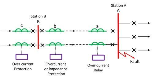
This is the simple way of protecting the bus-bar from the fault. The fault occurs on the bus-bar because of the supplying system. So the backup protection is provided to the supply system. The figure below shows the simple arrangement for the protection of bus-bar. The bus A is protected by the distance protection of the bus B. If the fault occurs on A, then the B will operate. The operating times of the relay will be 0.4 seconds.
The bus-bar protection system has few disadvantages likes the protection system is slow. Such system is mainly used for the protection of the transmission lines. But as the protection system is very economical, thereby it is also used for the bus-bar protection.
This protective scheme is not used for small switchgear system. The backup protection system has many disadvantages likes delayed in action, disconnections of more circuits for two or more transmission line requires etc.
Frame Leakage Or Fault-Bus Protection
This method insulates the bus-supporting structure and its switchgear from the ground, interconnecting all the framework, circuit breakers tanks, etc. and provided a single ground tank connection through a CT that feeds an overcurrent relay. The overcurrent relay controls a multi-contact auxiliary relay that trips the breakers of all circuits connected to the bus.
In such type of protection, the only metal supporting structure or fault-bus is grounded through a CT, secondary of which is connected to an overcurrent relay. Under normal operating condition, the relay remains inoperative, but fault involving a connection between a conductor and the ground supporting structure will result in current flow to ground through the fault bus, causing the relay to operate. The operation of the relay will trip all the breakers connecting equipment to the bus.
Differential Over Current Protection
Current Differential Protection
The current differential protection scheme works on the principle of the circulating current which states that the current enters into the bus-bar is equal to the current leaving the bus-bar. The sum of the incoming and outgoing junction is equal to zero. If the sum of current is not equal to zero, then the fault occurs in the system. The differential protection scheme is used both for the protection of the phase-to-phase fault and for the ground fault.
Schematic diagram of bus differential protection relay is shown in the figure below. The current transformers are placed on both the incoming and the outgoing end of the bus-bar. The secondary terminals of the current transformer are parallel connected to each other.
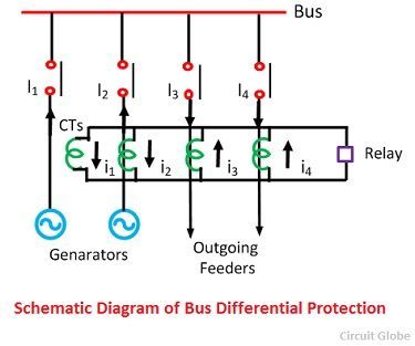 The summation current of the current transformer flows through the operating coil of the relay. The current flows through the relay coils indicates the short circuit current present on the secondary of the CTs. Thus, the relay sends the signal to the circuit breakers to open the contacts.
The drawback of such types of the scheme is that the iron cored current transformer causes the fault operation of the relay at the time of the external fault.
Voltage Differential Protection Relay
In this scheme, the coreless CTs are used. The linear couplers are used for increases the number of turns on the secondary sides of the CTs. The secondary relays connected in series with the help of the pilot wires. The relay coil is also connected in series with the second terminal.
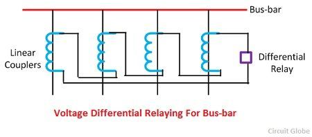 When the system is free from fault or external fault occurs on the system, the sum of secondary current of CTs becomes zero. On the occurrence of the internal fault, the fault current flows the differential relay. The relay becomes operative and gives command to the circuit breaker to open their contacts. Thus, protects the system from damage.
I need to understand the single bus bar with backup connection