Definition: The electrical drive system is defined as the system which is use for controlling the speed, torque and direction of an electrical motor. Each electrical drive system is different from other electrical drive systems, but there are some common features associated with all electrical drive systems.
Electrical Drive Systems
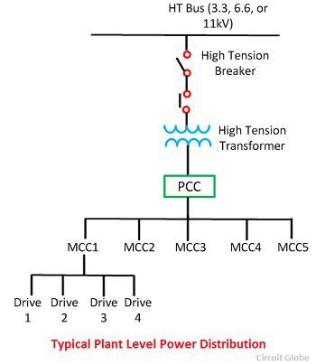
The figure shown below represents the typical layout of a plant level power distribution network.This electrical drive system receives its incoming AC supply from a Motor Control Center (MCC). MCC controls the power to few drives located in an area.
In a large manufacturing plant, many such MCCs exist and they receive power from the main distribution centre called Power Control Centre (PCC).The MCC and PCC normally used air circuit breaker as the power switching element. The ratings of these switching elements are up to 800V and 6400A.
The thermal overload relays protect the overload in the electrical drive system. The short circuit protection is provided by the magnetic sensing mechanism of the breaker. The high rupturing capacity fuses are used for the backup protection as well as for providing the protection against the fault occurring in the bus bar section before the circuit breaker.
Considered the example of two drive systems. One employs converter controlled DC motor and other inverter-fed AC motor. The converter controlled dc motor drive system is shown in the figure below.

The GTO inverter controlled induction motor drive is shown in the figure below:
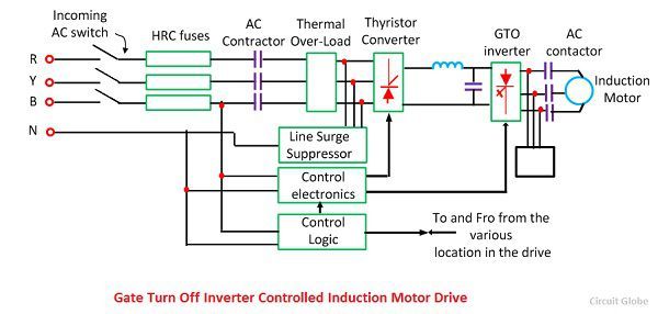
The following are the main parts of these drive systems:
- Incoming AC switch.
- Power converter and inverter assembly.
- Outgoing DC and AC Switchgear
- Control Logic
- Motor and the Associated Load.
The main parts of the electrical power system are explained below.
1. Incoming AC Switchgear: It consists a switch fuse unit and AC power contractor which have ranges up to 660V, 800A.The switch gear replaces the normal contractor by the bar mounted contractor and also used air circuit breaker as an incoming switch.The bar mounted contractor increase the range up to 1000V, 1200A.
It uses the HRC fuse whose rating is up to 660V, 800A. The AC switchgear consists thermal overload for protecting the system from overloading. Sometimes the contractor of the switchgear is replaced by the moulded case circuit breaker.
2. Power Converter/ or Inverter Assembly – This assembly has two major blocks – power and control electronics. The power electronics blocks consist of semiconductor devices, heat sinks, semiconductor fuses, surge suppressors, cooling fans. Control electronics consist of triggering circuit, its own regulated power supply and driving and the isolation circuit. The driving and isolation circuit controls and regulates the power flow to the motor.
When the drive operates in a closed loop, it will have a controller and current and speed feedback loops. The control system has three port isolation, i.e. the power supply, inputs and outputs which are isolated with adequate insulation levels.
3. Line Surge Suppressors – It protects the semiconductor converter against voltage spikes produce in the line due to on and off switchings of the load connecting on the same line. The line surge suppressor along with the inductance suppress the voltage spikes.
The line surge suppressor absorbs a certain amount of trapped energy when the incoming circuit breaker operates and breaks the current supplied to the trap. The line surge suppressor will not be required when the power modulator is not a semiconductor.
4. Control Logic – It is used for interlocking and sequencing of various operations of the drive system under normal, fault and emergency condition. The interlocking protects the system against abnormal and unsafe operations. The sequencing protects the various drive operations, such as starting, braking, reversing, jogging, etc., which are carried out in a pre-planned sequence. For complex interlocking and sequence operations, the programmable logic controller is used.
Hi All,
Say if I am to install an AC HV Motor, 55MW or larger, what drive system is commonly used?
Thanks
very nice