Definition: The transformer is the static device which works on the principle of electromagnetic induction. It is used for transferring the electrical power from one circuit to another without any variation in their frequency. In electromagnetic induction, the transfer of energy from one circuit to another takes places by the help of the mutual induction. i.e the flux induced in the primary winding is linked with the secondary winding.
Construction of an Electrical Transformer
The primary winding, secondary winding and the magnetic core are the three important of the transformer. These coils are insulated from each other. The main flux is induced in the primary winding of the transformer. This flux passes through the low reluctance path of the magnetic core and linked with the secondary winding of the transformer.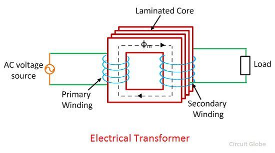
Transformer Working
Consider the T1 and T2 are the numbers of the turn on the primary and the secondary winding of the transformer shown in the figure above. The voltage is applied to the primary winding of the transformer because of which the current is induced in it. The current causes the magnetic flux which is represented by the dotted line in the above figure.
The flux induces in the primary winding because of self-induction. This flux is linked with the secondary winding because of mutual induction. Thus, the emf is induced in the secondary winding of the transformer. The power is transferred from the primary winding to the secondary winding. The frequency of the transferred energy also remains same.
EMF Equation of an Electrical Transformer
The emf induced in each winding of the transformer can be calculated from its emf equation. 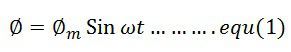
The linking of the flux is represented by the faraday law of electrmagentic induction. It is expressed as,
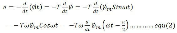
The above equation may be written as,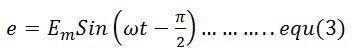
where Em = 4.44ωΦm = maximum value of e. For a sine wave, the r.m.s value of e.m.f is given by 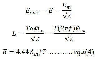
The emf induced in their primary and secondary winding is expressed as,
![]()
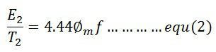
The secondary RMS voltage is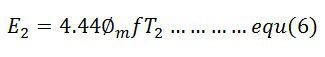
Where φm is the maximum value of flux in Weber (Wb), f is the frequency in hertz (Hz) and E1 and E2 in volts.
If, Bm = maximum flux density in the magnetic circuit in Tesla (T)
A = area of cross-section of the core in square meter (m2)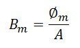
The winding which has the higher number of voltage has high voltage while the primary winding has low voltage.
Voltage Ratio and Turns Ratio
The ratio of E/T is called volts per turn. The primary and secondary volts per turns is given by the formula 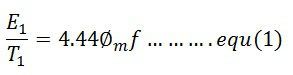
The equation (1) and (2) shows that the voltage per turn in both the winding is same, i.e.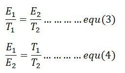
The ratio T1/T2 is called the turn ratio. The turn ratio is expressed as 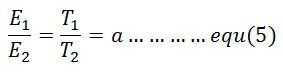
The ratio of primary to secondary turn which equals to primary to secondary induced voltage indicates how much the primary voltage lowered or raised. The turn ratio or induced voltage ratio is called the transformation ratio, and it is denoted by the symbol a. Thus,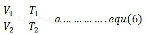
The any desired voltage ratio can be obtained by shifting the number of turns.
Could you please refer about on load tap changing
very informative article
good article
impressive post
Thank u so much. This is a great article 😀😁😄😃