The Deep Bar Rotor in an induction motor is used to obtain high rotor resistance at starting and low rotor resistance at the running condition.
The figure below shows a deep bar cage rotor with deep and narrow bars:
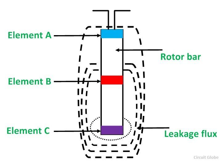
A bar may be assumed to be made up of a number of narrow layers connected in parallel. The above figure shows three layers A, B, and C. The topmost layer element that is denoted by A is linked with the minimum leakage flux. Its leakage inductance is minimum. On the other hand, the bottom layer C links with the maximum leakage flux, and thus, its leakage inductance is maximum.
At the starting, the frequency of the rotor is equal to the supply frequency. The bottom layer element C offers more impedance to the flow of current than the top layer element A. Therefore, maximum current flows through the top layer, and minimum current flows through the bottom layer.
The effective rotor resistance increases and the leakage reactance decreases, and this is because of the unequal current distribution of the current. The starting torque and the starting current are higher and lower, respectively because of the high rotor resistance at the starting condition.
The value of a slip and the frequency of the rotor is very small, under normal operating conditions. The reactances of all the layers of the bars are small as compared to their resistances. The impedance of all layers of the bar is nearly equal, so the current flows through all parts of the bar equally. The rotor resistance of the motor is small because of the large cross-sectional area, which results in a better efficiency at the lower slip.
Thanks..