In closed loop system, the output of the system is feedback to the input. The closed loop system controls the electrical drive, and the system is self-adjusted. Feedback loops in an electrical drive may be provided to satisfy the following requirements.
- Enhancement of speed of torque
- To improve steady-state accuracy.
- Protection
The main parts of the closed-loop system are the controller, converter, current limiter, current sensor, etc. The converter converts the variable frequency into fixed frequency and vice-versa. The current limiter limits the current to rise above the maximum set value. The different types of closed loop configuration are explained below.
Current Limit Control
This scheme is used to limit the converter and motor current below a safe limit during the transient operation. The system has a current feedback loop with a threshold logic circuit.
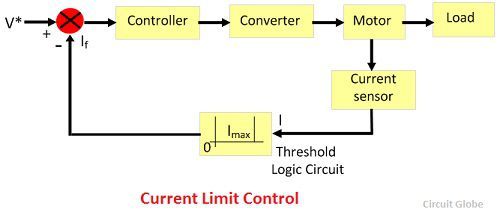 The logic circuit protects the system from a maximum current. If the current is raised above maximum set value due to a transient operation, the feedback circuit becomes active and force the current to remains below the maximum value. When the current become normal, the feedback loop remains inactive.
Closed-Loop Torque Control
Such types of loop are used in battery powered vehicles, rails, and electric trains. The reference torque T* is set through the accelerator, and this T* follows by the loop controller and the motor. The speed of the drive is controlled by putting pressure on the accelerator.
 Closed-Loop Speed Control
The block diagram of the closed loop speed control system is shown in the figure below. This system used an inner control loop within an outer speed loop. The inner control loop controls the motor current and motor torque below a safe limit.
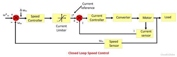 Consider a reference speed ω*m which produces a positive error Δ ω*m. The speed error is operated through a speed controller and applied to a current limiter which is overloaded even for a small speed error. The current limiter set current for the inner current control loop. Then, the drive accelerates, and when the speed of the drive is equal to the desired speed, then the motor torque is equal to the load torque. This, decrease the reference speed and produces a negative speed error.
When the current limiter saturates, then the drive becomes de-accelerate in a braking mode. When the current limiter becomes desaturated, then the drive is transferred from braking to motoring.
Closed-Loop Speed Control of Multi Motor Drives
In such type of drive, the load is shared between the several motors. In this system, each section has its own motor which carries most of its load. The rating of the motor is different for the different type of load, but all the motor run at the same speed. If the torque requirement of each motor is fulfilled by its own driving motor, then the driving shaft has to carry only small synchronising torque.
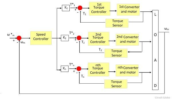 In a locomotive, because of different amount of wear and tear the wheel of the locomotive revolve at the different speed. Thus, the driving speed of the vehicle also vary. Along with speed, it is also essential that the torques are shared equally between the various motor; otherwise, the one motor is fully loaded and another, is under loaded. Thus, the rated locomotive torque will be less than the sum of the individual motor torque rating.
Nice content, and easy to understand.